THE AES/EBU PIPELINE
In the early days of digital audio we lacked a reliable means of passing signals between devices in digital form. An error in the handoff is a show-stopper (literally). Compatibility issues, format wars and bleeding edge implementations made the digital-digital hookup a risky business. We still wanted all the benefits of internal digital processing without the downside, which meant the surest way to getting console ABC to drive speaker processor XYZ was to bail out back to analog. Therefore it was common for our signal chains to be a series of digital islands connected by analog seas. It is obvious that multiple A/D and D/A conversions in our signal path will degrade the audio quality. Standardization of format, wiring practices and data packaging provided a way forward to reliably move digital audio streams between devices made by different manufacturers at different times.
We can now transmit digital audio between devices without conversion back to analog. We need to follow the instructions and pack it up for transport. AES3 is the standard protocol used for various formats and mediums. The core packaging method is universal within the industry and then applied in various highly compatible forms. Two-channel and multi-channel versions are found in wire and optical formats.
Digital audio transmission is point-to-point communication, with no allowance for splitting output signals to multiple inputs (unlike analog transmission). This is essentially RF communication so some connectors and cabling are the same as used in RF and video.

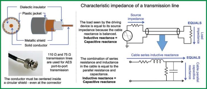
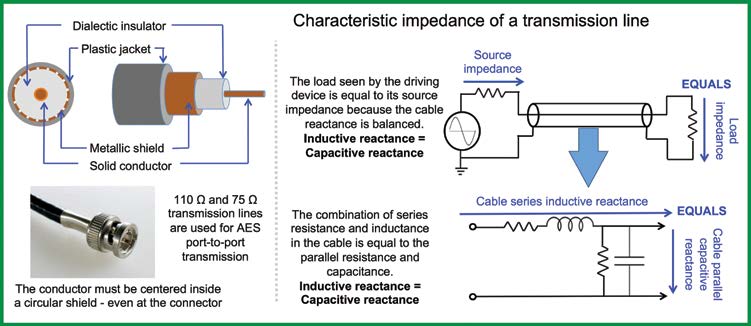
The standard electrical interconnection between AES output and input is a 75Ω or 110Ω cable. These cable impedances sound very high for those of us in the analog frame of mind. Especially for a 1m cable! And why is it the same impedance for a 10m cable? The impedance specified for digital transmission is a completely different animal from the length-proportional series resistance, inductance and parallel capacitance that we see adding up in our analog signal cables. The 75Ω specification is the “characteristic impedance,” a function of the cable’s cross-sectional anatomy, not its length. The difference between 75Ω and 110Ω rated cable is the conductor diameter and the spacing and dielectric (insulating) material between it and the shield, not the length. Characteristic impedance is strongest with a single conductor in the center of a circular shield: a coaxial cable. Analog cables also have characteristic impedances (22 AWG is around 70Ω), but we’re not driving 20 kHz bandwidth for a mile or transmitting 6MHz. That’s why we never worry much about characteristic impedance, but the telephone industry certainly did before fiber took over.
Standard analog audio transmission uses low impedance sources to high impedance receivers. This is RF transmission through a cable whose impedance closely matches the source and receiver, the “transmission line.” It’s a balanced line, but in a totally different way than line level audio: impedance balanced. The series impedance (resistance+inductance) equals the parallel impedance (resistance+capacitance). This creates a nearly lossless transmission, with minimal reflections in the cable (Fig. 1).
In the pro audio analog world we don’t think about reflections in a cable, but some of us are old enough to remember them during long distance phone calls. Reflections become a concern when transmitted wavelength approaches cable length. This is 1156m @ 20 kHz for analog electronic circuits, so no problem there. We are working in the 6 MHz range and up here. A reflection in the digital audio transmission line won’t cause an audible echo like its analog counterpart. Instead it creates additional data that impersonates the original, a form of aliasing that can cause transmission errors that render data unreadable. Terminating the cable at the characteristic impedance dampens the reflection at the destination.
Navies have long used wireless communication to send encoded optical digital audio between vessels: a seaman flashes Morse Code by opening and closing the shutters on a light. Fiber optic digital audio is much faster, but the concept is the same. When an optical transmission system is on the blink, it’s working correctly. Optical digital transmission substitutes light for voltage. The cable has a virtually lossless internally reflective skin. Optical cable can run multiple channels as well by multiplexing (running multiple signals in series and decoding them separately). Optical signals are free of ground looping issues and can be hotpatched without fear or surges. Care must be taken to prevent hard bends in optical cable runs as this breaks the reflective path (Fig. 2).
AES COMPATIBLE CONFIGURATIONS & STRUCTURE
AES/EBU (AES3) is a two-channel configuration. Standard AES3 cable is 110Ω 3-conductor twisted pair with a maximum recommended length of 100m. The XLR and RCA connectors themselves underwent analog to digital conversion and were recycled for AES3. I guess this seemed like a good idea at the time but can lead to mis-patching. The connectors fit in the holes, but the cable is not compatible and leads to unexpected results in both directions. Conclusion: verify your cable.
Each audio sample carries a single numerical value in 16 to 24 bits. Each data frame needs identifying markers to keep it in order. It would be very inefficient to individually wrap every frame of every channel. Instead they are grouped in sets of 192 frames, which at 48 kHz amounts to 4ms of audio (0.02083ms x 192).
The end product is an “audio block”: two channels with 192 audio frames and a complete set of packing materials. Let’s see how we get there.

The converted audio sample is packed into 32 bits to make an audio frame. The middle 24 bits (the audio bits) are the magnitude values in fixed-point decimal form. Let’s call these 24 bits the audio bits, and the other 8 the packing bits for ease of discussion. Eight packing bits and 24 audio bits give us a single subframe (one of two channels). Join the subframes together to make a complete frame (64 bits of audio data and info). We continue this operation 191 more times and wrap it all up into an audio packet.
Each audio block requires 64 serial operations before the next sample (32/subframe). Operations are divided into time slots managed by the bi-phase mark coding clock (BMC), which is much faster than the word clock. As an example, for 48 kHz we have 64 bits x 48 kHz = 3,072 kb/sec with a biphase clock of 6.144 MHz.
How much time is represented by an audio block? This depends on sample rate. 192 frames of 48 kHz audio is 4ms of audio, a frame rate of 250 Hz. Double that for 96 kHz and again for 192 kHz (Fig. 3).
Let’s return to the 32-bit subframe. The audio bits contain 192 unique 24-bit numbers: the audio data stream. We now have a grid of audio values (24 bits amplitude vs. 192 bits time). All formats share the most significant 16 bits and the 20- and 24-bit data fills in the lower bits. The 16- and 20-bit formats send all 0’s to the unused lower bits. This grid is the payload for an audio block.
Some of the packing bits are handled differently. They are spread over the 192 frames as 24 words of 8-bytes each (24 x 8=192) to tell us the story of this audio block. Audio bits are read vertically, subframe-by-subframe, and packing instructions are read horizontally over the 192 subframes. This spreads the packing info over the audio block, much higher efficiency than sending complete notations on every frame.
The eight packing bits are divided in two sections: pre and post. Bits 0-3 are the preamble, preparing to sort the incoming data. Here comes the first frame of channel A. Next is a frame from B, etc. The last four bits follow the audio data. Bit 28 checks to see if the data is ready for D/A conversion and puts in a stoporder if not. Bit 31 is the parity bit, the basic transmission error checker.
The main event for packing is bit 30, the “channel status bit” which has enough detailed information to correctly decode and find this audio needle in a haystack of over 17 million packets. That’s over 12 hours of continuous audio at 96 kHz (we can transmit the soundtrack for the “Lord of the Rings” films without repeating the index number). Also included in this bit is embedded SMPTE time code. You might wonder how we get this done in just eight bits since it takes a 32-bit word to do each time code. It’s the payoff for spreading the words over the entire block instead of putting it all on each subframe.

The main AES/EBU compatible formats include:
- TOSLINK: Toshiba Link (TOSLINK) is a short distance (<10m) fiber optic version of AES3. Toshiba, SP/DIF (Sony Philips Digital In Format). The connector is the JIS F05.
- S/PDIF: The Sony/Philips Digital Interface Format (S/PDIF) is a short range, unbalanced consumer implementation of AES3 with a lower voltage reference standard. The wired version uses 75Ω coaxial cable with RCA connectors and the optical version uses the TOSLINK connector.
- ADAT Lightpipe (ADAT Optical Interface): a multichannel optical format initially implemented by Alesis for their ADAT recorders but also used by others. The connector is the same as TOSLINK and S/PDIF but the protocol is not compatible. The Lightpipe has a fixed capacity but can be resource allocated by number of channels at a given sample rate. For example, 8 channels at 48 kHz, 4 channels at 96kHz.
- MADI (AES10): Multichannel Audio Digital Interface (MADI) can transmit multiple channels of uncompressed AES compatible audio. The exact channel count will vary by sample rate but 56-64 channels of 48kHz of 24-bit audio are normal. The channel count is reduced by half at 96 kHz. The connections and cabling for both the electrical and optical formats are the same as the 2-channel version (AES3) so the cable and connector savings are substantial. MADI adheres to the AES10 standard and has widespread manufacturer support. Cable lengths can reach a maximum recommended length of 100 to 3000 meters.
DIGITAL TO ANALOG TRANSMISSION
We had our fun in the digital world but now it’s time to return to planet analog. The converter constructs an analog waveform from the final digital number sequence. We don’t need to start from zero on this, since many of the processes are a reversal of the A/D previously discussed.
Recall that our AES audio block has a bit that checks whether the sample is convertible, our version of transportation security. The package is inspected to ensure there’s no bomb in there. If it detects a problem that can’t be error-corrected then “no sound for you!” As bad as that is, it beats a digital sonic boom.
The signal must be packaged and delivered to the D/A converter in a ready state: a fixedpoint numerical series with known format, bitdepth, bit-order, clock frequency, etc. All 192 samples must be in chronological order.
RETURNING TO ANALOG WORLD
We need an exit side sensitivity reference (the inverse of the entry side). It’s often a user-settable parameter. At this point full-scale digital creates (rather than reads) a certain voltage. It’s dBFS on the input side, so maybe we should call it FSdB (probably not, since nobody else does). The dBFS on the A/D and D/A sides don’t have to match. Each can be optimized for best conversion with the upstream and downstream devices respectively. In pro audio we can expect to convert into an analog system with standard line level capacity (+20 dBV) also known as -20 dBFS = 1V (0 dBV). Maximum analog and maximum digital will match if we target the dBFS to this range. Lower values require added analog gain after conversion to reach full-scale analog (Fig. 4).
It’s time to play “connect the dots.” This won’t be as simple as the childhood game where we draw the shortest, straightest line between the numbered sequence of dots. Let’s begin by understanding what happens if we do nothing, and then move on to how to solve it.
If we follow the digital instructions literally we would hold the present voltage value for the entire sample period and then BOOM, move almost instantly to the next setting (like a square wave). This is called a “step function” since it resembles a stairway. We can’t ask the analog device to reproduce the sharp transition of a step function. To do so creates harmonics that were not part of the original signal. We are facing aliasing again from the opposite direction because a step function would create the distortion of out of band harmonics.
Instead we connect the dots with curves that smooth the transitions into shapes that are organic to harmonic motion in the physical world. We know we are pushing a speaker around so let’s round the edges to make it possible to faithfully track. A step function is a recipe for failure for a loudspeaker. It has mass, momentum, compliance, back EMF, and more to prevent it from an instantaneous change from rest to full excursion. The speaker won’t track the step function so let’s help it out as best we can.

The mathematical process is termed the “reconstruction filter” which examines each step transition and applies a smoothing algorithm to best-guess approximate analog signal behavior. Each D/A model approaches this interpolation differently, a “leap of faith” between two known points. This is obviously a critical quality differentiator in the perceived audio quality of converters. How can we tell if the interpolation was a good guess? We would need to compare an analog original to its analog to digital to analog copy (Fig. 5). This includes two conversions and everything in between, so it’s difficult to isolate one single cause, but the differences (known as quantization errors) can be found as long as we are just passing the signal through the digital system (and not mixing, filtering etc.). Everybody interpolates differently, so from a marketing perspective we can go with the slogan: “My error’s better than your error.”
This concludes our two-part series on digital audio transmission. We covered the path from analog to digital, the opportunities for digital processing and ultimately the return to analog form. There is, of course one more major player in this field, the digital audio network. These networks move digitized signals in bulk between devices. They are like the multi-channel superhighways of our digital audio transmission world, moving vast amounts of data at breakneck speeds. And indeed they are exactly that: transportation systems, moving packages of data from place to place. Like shipping a package, we expect it to arrive the same as it left, i.e. we are not intending to modify it, filter it or process it in transit. Just pack it and ship it. Therefore, this is a subject in and of itself that we can cover another day