Adventures In RF Design
The impending transition from analog television to digital television (DTV) brings with it many problems and issues that have yet to be resolved, the biggest of which may be education.
The impending transition from analog television to digital television (DTV) brings with it many problems and issues that have yet to be resolved, the biggest of which may be education. DTV not only requires a working knowledge of MPEG, but also one of radio frequency (RF), a frequency or rate of oscillation within the range of about 3Hz and 30GHz.
As an industry, we tend to take RF signal acquisition and distribution for granted. At the courses I teach at InfoComm on RF fundamentals for systems integrators, the only attendees that typically have a working knowledge of RF are most often the long-time ham radio hobbyists. My class, which features many hands-on demonstrations, is usually lightly attended. Yet, as an industry, we cross paths with RF on a regular basis. In my opinion, we can’t simply depend on specialized manufacturers to come up with solutions to RF signal distribution problems for us. We’ve got to have some basic RF “smarts” of our own.
One of the demonstrations at this year’s InfoComm class in Anaheim, Calif., was to acquire terrestrial DTV signals from Mt. Wilson, which is about 30 miles away. It was done indoors with a UHF yagi and preamplifier. At least 14 different signals came through successfully — even with moderate to severe multipath from all of the echoes and reflections in the building.
I used multistage bandpass/band-reject filters to extract three signals on UHF channels 31 (KTLA), 36 (KNBC), and 53 (KABC) while filtering out all other parts of the UHF spectrum. Finally, I recombined those three signals into one RF stream, in essence, creating a private selective digital TV distribution system.
At last year’s show in Orlando,Fla., I was also able to extract several digital cable channels and multiplex them with filtered-out channels from the local ABC and CBS affiliates, creating a multimode RF backbone. It would have been a simple matter to inject additional custom RF channels from low-power 8VSB or QAM modulators. For that matter, any of the VSB or QAM channels could have been demodulated and remodulated to entirely different channels.
The tools to do all of this are available off-the-shelf from companies such as Microwave Filter in Syracuse, N.Y., and Blonder Tongue in Old Bridge, N.J. The trick is selecting the right filters for the job.
Filter Types
A filter is nothing more than a collection of discrete or etched circuit components that resonate at a specific frequency or frequencies, but block signals at others. The most common types are series resonant and parallel resonant; all other filter designs are adapted from these two building blocks. In a series resonant circuit, the impedance at the desired frequency is low, and signal levels are passed with maximum voltage.
In contrast, a parallel resonant circuit provides a high-impedance obstruction to signal flow, resulting in minimum signal voltage at the desired frequency or frequencies. By applying these two designs carefully, we can move RF anywhere we want — even in opposite directions at the same time.
We can design a high-pass filter that presents a low impedance above a specific frequency, allowing us to block all signals below that frequency. Conversely, passing all signals below a specific cutoff frequency would be the job of a low-pass filter.
If we wanted to toss out an unwanted signal or band of signals, but allow other signals above and below the affected region to sail through, we’d opt for a trap filter for a single frequency or a band-reject filter for a range of frequencies.
Thinking the other way, a bandpass filter would be the ticket for allowing one or more signals in a narrow range to get by while blocking all other signals above and below that range. By adding more stages of filtering, we can make our filters quite selective and increase the signal rejection for unwanted RF.
The Real World
My family summer home in Canada can receive both analog and digital TV signals from the United States and analog TV stations from the Canadian side. The U.S. digitals are all on UHF channels, and some come from as far away as Syracuse, N.Y. — an 80-plus mile path.
I installed a Channel Master 4308 suburban UHF yagi and a Titan 2 UHF preamp, aimed south-southeast, to pick up nine ATSC and a handful of NTSC UHF carriers. A Radio Shack-amplified, bar-style TV antenna takes care of the analog VHF broadcasts, but this antenna also pulls in UHF signals.
A simple diplexer with bandpass at UHF frequencies and band-reject characteristics at VHF frequencies allows me to isolate UHF reception on the Channel Master antenna. Only the VHF channels come through from the bar antenna, and both RF paths are combined into one master feed to three different TVs in the house.
At home in Doylestown, Pa., I experimented with pulling in selected New York City DTV stations on UHF channels by installing highly selective, single-channel bandpass filters. These allowed me to then multiplex these additional channels back into my house RF feed. The filters were necessary to trap out any out-of-phase signals received off the back end of the New York City antenna, which would have caused signal dropout.
The same trick could be used to receive signals off-axis from the primary master (MATV) antenna. I often get inquiries about hooking two antennas up through a splitter, back-to-back, to pull in stations that are nearly 180 degrees opposite. It sounds like a good idea, except that signals received off the back of each antenna will be out of phase with the same signals received off the front of each antenna, resulting in cancellation.
In this case, the best practice is to install multiple antennas with tight bandpass filters for each desired channel — or use a broadband RF amplifier and then split the signals into separate bandpass filters, recombining them at the far end for multiplexing. The same procedure would be followed for the second antenna.
In a case where DTV stations are about 90 degrees apart, you can sometimes get away with a simple hybrid combination of both antennas into one RF feed. That’s because the minimum signal lobes for directional antennas are located at 90 degrees to the axis of the antenna, which results in better than 20 dB of isolation at UHF frequencies.
Similar nulls are seen with multi-element, high-gain VHF antenna systems. However, simple dipole antennas, such as the “bar” type I used in Canada, don’t have such pronounced nulls, so simply combining both antenna feeds through a two-way splitter may result in interference between the two antenna patterns.
To Amplify or Not to Amplify
It’s all too easy to add an amplifier to any RF system to kick up signal levels. The problem is, not all amplifiers are created equal. Therefore, you may be making new problems for yourself by indiscriminate use of amplifiers. The best way to use any amplifier is to figure out how much signal you want at each RF tap and work backward from there. If you’ve got low signal levels from a residential cable TV or MATV feed, an amplifier is definitely in order, as long as the incoming signal doesn’t overdrive the amplifier.
In my house, I split the feed from the local cable company three ways after processing through a +15 dB broadband amplifier. I originally used a dual-output +22 dBm broadband amplifier to drive four 75-ohm feeds through my house, but discovered that the amplifier wasn’t “flat” from 50MHz to 800MHz. In fact, it had a pronounced roll-off of about 20 dB between 275MHz and 400MHz. Needless to say, that made reception between channels 33 and 54 problematic, most notably on channels 40 through 46.
In practice, a broadband amplifier should have essentially flat frequency response across its specified range. Output shouldn’t vary by more than 3 dB from low frequencies to high frequencies. The best way to measure amplifier response is with a broadband RF noise source and a spectrum analyzer. As it turned out, the amplifier was labeled incorrectly. It was actually a dual-band VHF/UHF amplifier, which would explain the drop-off in signal levels mentioned above.
Assuming the RF noise source is flat, you’ll spot any problems right away. If you see a variation of more than 3 dB to 4 dB across the range of the amplifier, don’t use it. Your incoming RF signals may vary by a greater amount, and the amplifier won’t help you much on weak signals.
Another important consideration is to avoid overdriving the input of the amplifier. This means you may have to install fixed 75-ohm attenuators or “pads” at the input to ensure the amplifier doesn’t become saturated and possibly go into oscillation or produce unwanted harmonics. Again, a spectrum analyzer is the ticket to clearly seeing what’s going on with amplifier problems. Simple signal level meters can’t tell you if a signal is distorted or unwanted — only how strong it is.
It’s also a good idea to pad the output of an amplifier to make sure it’s driving into a constant impedance load. Most splitters are close enough to 75 ohms, but you could add 3 dB of inline attenuation as a “buffer” to ensure whatever changes happen to your RF system beyond that point (wanted or unwanted) don’t affect the amplifier’s performance.
Up on the Roof
RF amplifiers installed at an antenna are vastly different in performance than those intended for broadband RF distribution. Mast-mounted designs will have more gain as well as a much lower noise figure. The noise figure is important because the more noise you carry in your RF system, the lower the carrier-to-noise level you’ll have at the output. That translates into lower signal levels and dropout.
A generic, low-cost consumer-grade RF amplifier, such as those found at home improvement and Radio Shack stores, will typically have a high noise figure and is not likely to provide flat frequency response. Noise figures could range as high as 6 dB to 8 dB and will add to any other noise in your system, causing overall performance to deteriorate. A premium-quality amplifier will show a noise figure below 4 dB. The Channel Master Titan 2 UHF preamps I use have a specified noise figure of about 2.5 dB, which is excellent performance at 800MHz. I use them for signal runs in excess of 50 feet or when I know I have to split the incoming RF signals two times or more.
The signals from those amplifiers (typically 24 dB to 26 dB of gain) do not go into secondary distribution amplifiers in my RF system. The reason? It would seriously overdrive the secondary amplifiers and create all kinds of problems with unwanted harmonics and square waves. Instead, I simply split and tap off the mast-mounted antenna signals and multiplex as needed.
One scenario to avoid is cascading two roof-mounted amplifiers. That’s a sure-fire recipe for disaster; the first amplifier would produce such strong signals that it would drive the second amplifier into oscillation or even damage the front end. It’s easier to pick up another 3 dB of signal by stacking a second antenna atop the first one.
Setting a Trap
No matter how well you design your RF system, there’s always some little “bugger” of a signal that manages to get inside and create havoc with one or more of your desired channels. In that case, you’ll need a very tight filter that chokes the intruder right out. Such a filter, known as a single-frequency trap, is handy for eliminating interference from a nearby radio station, two-way radio service or repeater, or even spectral garbage from power lines, computers, or other consumer electronics. The filter is designed to have steep skirts and lots of attenuation at the problem frequency while leaving adjacent channels largely unaffected.
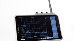
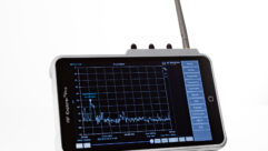
To find the offender, you’ll definitely need a spectrum analyzer connected to your RF distribution system and any antennas connected to it. Again, a simple handheld RF signal level meter won’t tell you anything other than signal levels. You’ll need to look at the spectrum in question and isolate the intruder, often by using a switchable precision attenuator to drop ambient RF signal to near zero.
Broadband interference is another issue. I did an RF site survey in Glendale, Calif., a few years back that showed a broadband “hash” starting at channel 39 and extending to approximately channel 60. This hash raised the noise floor by 22 dB at its worst and made terrestrial DTV reception impossible.
The solution didn’t involve any filters, just some basic RF detective work. Swinging the antenna revealed the noise source to be peaking to the north and southwest. Because it had a directional characteristic, I was able to position the rooftop UHF yagi antenna (and another Titan 2 UHF preamp) to null out the noise while simultaneously peaking the DTV signals from Mt. Wilson.
This involved slowly walking along the roof with a small spectrum analyzer, checking for a null in the noise while maintaining clean 8VSB waveforms. The “sweet spot” was located in less than 2 minutes, and the antenna was fixed in this location. A total of 18 DTV signals were then received with no hiccups on any UHF channel.
Final Thoughts
It isn’t all that difficult to learn how to “tame” RF and get it where you want it to go. A basic knowledge of filters is a must, along with amplifier theory, signal propagation basics, and fundamentals of transmission lines and cables.
One very useful industry reference is the Blonder Tongue’s Broadband Guide, which is a handy pocket-sized guide full of tables, frequency allocation data, and field reference material. You can generally get these at little or no charge from the company (www.blondertongue.com). Be sure to also ask for its broadband CD-ROM, another handy reference tool to have around.
Pete Putman, CTS, ISF, is a contributing editor for Pro AV and president of ROAM Consulting, Doylestown, Pa. Especially well known for the product testing/development services he provides manufacturers of projectors, monitors, integrated TVs, and display interfaces, he has also authored hundreds of technical articles, reviews, and columns for industry trade and consumer magazines over the last two decades. You can reach him at[email protected].


