Hanging out in Las VegasThe renovation of downtown Las Vegas brings sparkle and entertainment to “Glitter Gulch.”
Dec 20, 1996 12:00 PM,
Frederick CurdtsCurdts is senior vice president and vice president of engineering at Signal Perfect
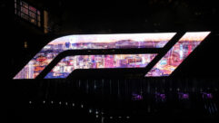
Imagine a graphics display board four city blocks long with 2.1 million multicolored lights. It is suspended 100 feet over your head, integrated into a space frame canopy also covering four city blocks. It has full-color, computerized graphics and animation and more than 500,000 W of concert-quality sound reinforcement to complement the video display.
This is the Fremont Street Experience, which opened last year in downtown Las Vegas. It was a project on a grandiose scale, one that might only be found in Las Vegas, and has already become the centerpiece of the city’s downtown revival. The sound system for the attraction has 52 full-range loudspeaker clusters aligned in stereo pairs along the 1,500 foot (457 m) length of the attraction.
Physical descriptionFremont Street is the main street of the original downtown Las Vegas. The Experience starts at Main Street at the Plaza Hotel and continues down Fremont Street to Las Vegas Boulevard. Along the way it passes The Golden Gate, The Golden Nugget, The Horseshoe, The Four Queens, The Fremont Hotel, Fitzgerald’s and other notable and historic establishments.
As part of this project, this four-block section of Fremont Street was converted into a pedestrian mall covering slightly more than four acres. The canopy housing the graphics display system and supporting the loudspeaker clusters is five feet (1.5 m) deep with a radius of 44 feet (13 m). At its center point, the canopy is 95 feet (29 m) above the street. The canopy is supported in this position by 16 40 inch (1 m) diameter steel and concrete columns spaced on 200 foot (61 m) centers along both sides of the street. The pairs of loudspeaker clusters are suspended from the canopy on 50 foot (15 m) centers, with one cluster on either side of the street. Each loudspeaker cluster contains three full-range cabinets and one sub-bass cabinet for a total of 208 cabinets.
Loudspeaker system designPaul S. Veneklasen & Associates, Santa Monica, CA, did the conceptual cluster design in conjunction with JPI Architects of Venice, CA. Signal Perfection Ltd. (SPL), based in Columbia, MD, was responsible for the engineering and installation of the system.
The engineering of the loudspeaker cluster system for Fremont Street had several concurrent aspects. One was to design a cluster assembly that supported the necessary loudspeaker components, provided the desired coverage and met the aesthetic requirements of the project. The second was to design an attachment and suspension method for the cluster assemblies – the canopy vault height ranged from 75 feet to 95 feet (23 m to 29 m), and the loudspeaker clusters had a trim height of 25 feet (7.6 m). The third was to devise a method to prevent the clusters from moving laterally once suspended. The fourth was to develop a method of erecting the clusters.
Loudspeaker cluster designEach loudspeaker cluster consisted of three EAW KF695 full-range loudspeaker cabinets arrayed over 180°, augmented by a Community VBS415 subwoofer. The loudspeakers were to be held in a 10 foot (3 m) diameter tubular ring, an architectural feature of the Experience. The ring contained the structure that held the loudspeaker cabinets and allowed each full-range loudspeaker to aim downward at a 50° angle.
The subwoofer sits on top of the frame. (See Figure 1.) In addition to the functional and aesthetic requirements, SPL had to consider gross weight, manufacturability and transportability in the design criteria. The canopy supporting the clusters had a strict loading limitation of 2,000 pounds (900 kg) per node, so the frame and support hardware holding the loudspeaker cabinets could not exceed that limitation less the weight of the loudspeaker cabinets themselves.
It also became apparent after investigation that the cluster frames would need to be made outside of Las Vegas and transported via truck; therefore, overall size was a critical factor. The first step in the design process was to do a 3-D physical model of the loudspeaker clusters and the steel frame using a CAD program. This allowed us to manipulate the loudspeaker aiming angles and gave us dimensional information, loudspeaker mounting points, center of gravity and weight for the frame. The loudspeakers and listening areas were also modeled using an acoustical modeling program. This exercise confirmed that we had the proper splay and downward angles, which allowed us to fix the loudspeakers rigidly within the frame without any concern for reaiming them after installation.
After a design was finalized, SPL retained ATM Fly-Ware, Carson, CA, to build a prototype of the loudspeaker assembly. The prototype was assembled in ATM’s facility in California, tested, disassembled and transported to Las Vegas for an in-place demonstration. A 50 foot (15 m) crane lifted and held the prototype cluster, complete with amplifiers and wiring harnesses, for all to critique. After several hours of testing, lots of interested bystanders and a few minor adjustments, it was good-to-go. The architect had one caveat – no turnbuckles or other leveling devices would be accepted. This made the subsequent tasks more difficult. ATM was contracted to build the 52 cluster frames, and SPL proceeded with the next task: designing an attachment method.
Cluster attachment and suspensionWith the cluster design now finalized and the weight trimmed to less than the required 2,000 pounds, the real work began. The space frame that created the canopy had a series of nodes where the various struts intersected. These nodes, which were the load-bearing points that would support the clusters, had a single-point load limitation of 2,000 pounds.
A fairly straightforward single-point hang was developed that uses a 50 foot (15 m), 1/2 inch (13 mm) steel cable drop that bridled out to a four-point suspension for each cluster. A custom eye-hook assembly attached the cable to the space frame (see Figure 2), and life was good. That was until the manufacturer of the space frame, after analyzing the weight of the graphic display system, down-rated the acceptable weight of the loudspeaker cluster assembly for a single-point hang to 1,500 pounds (675 kg).
The loudspeakers and the cluster frame weighed more than 1,500 pounds, and that did not include the support cables, loudspeaker cables, conduit and hardware. Life was suddenly not so good.
A two-point, triangular suspension method was then designed. This solved the vertical loading problem by distributing the 2,000 pound weight evenly over two points, but now the lateral loading on the attachment points came into play, and the attachment brackets had to be redesigned. The architect then determined that the two-point method was unacceptable because the large loudspeaker cable conduit attached to one of the two drops created an asymmetrical appearance. A third hang point was added, creating a three-point, coplanar suspension – envision an inverted isosceles triangle with a line bisecting its base and connecting to its tip. Changing from a single-point drop to a three-point drop, with the loads shared among the three legs, required an extensive computer model. (See Figure 3.) Deflections of the cables and the frame attachment points had to be calculated in order to determine the exact length the cables needed to be for each cluster. Once the cable lengths were calculated, the cables were prestretched, cut and crimped to length with a tolerance of ±1/16 inch (1.6 mm). (Remember, no turnbuckles or other adjustments were allowed.) The prefabricated cables were finally hung in place to await the arrival of the loudspeaker cluster frames.
Designing the lateral supportWith the attachment points for the clusters about 85 feet (25.9 m) above grade and the loudspeaker clusters hanging at 25 feet (7.6 m) above grade, we now had a 60 foot (18 m) pendulum with a 2,000 pound “ball” at the end. Outdoor structures in Las Vegas are required to withstand wind loads of up to 90 miles per hour (145 km), and that requirement applied to the loudspeaker clusters. With a cross-sectional area of more than 50 ft2 (4.6 m2), these clusters offered quite a gathering surface, and the potential wind-load forces were significant. The addition of the two vertical support cables had alleviated the problem of rotation and had also helped prevent lateral movement in one direction, but lateral movement in the other direction was still a problem; to picture this, think of a child’s swing. This direction of movement was perpendicular to the length of the street and, therefore, directly at the facades of the casinos that faced the streets. Some of the expensive neon signs adorning these casino fronts were less than 1 foot (305 mm) from the outer edge of the cluster frames. The only structures offering an anchoring point for lateral support of the loudspeakers were the columns that supported the canopy. As previously described, these columns are about 200 feet (61 m) apart, and four clusters were between each pair of columns.
The solution turned out to be a pair of prestretched, post-tensioned 5/8 inch (16 mm) steel bridge cables running horizontally between the columns and anchored to the outer sheath of each column. The cable and tensioning system is similar to that used to post-tension concrete slabs in buildings. The custom blocks welded to the outer sheath of the column anchor the cables to the columns. The cables were pulled through the blocks and then tensioned to 12,000 pounds (53.4 kN). Spreader bars were placed between the cables during the tensioning process to keep them spaced at a distance equal to the outer diameter of the clusters. The tensioned cables were then clamped with a chuck to lock them in place and maintain the 12,000 pound force on the cables. The clusters were equipped with U-bolt anchor plates to grab the horizontal cables as they went by each cluster. (See Figure 4.) The final result is that the lateral support system prevents the clusters from moving any more than 4 inches (102 mm) in any direction and keeps the neon glowing in downtown Las Vegas.
Erecting the clustersWith all of the support cables already in place, lifting and attaching the loudspeaker clusters was the final piece of the construction. Structural engineers know that the erection process is the most difficult and risky phase of any project. During erection, loads are dynamic, and bearing members may be subject to loads greater than the design loads until the structure is stabilized.
At Fremont Street, the horizontal cables placed to provide lateral support for the loudspeakers required careful attention. A vertical load of only a few hundred pounds inadvertently imposed on these horizontal cables could result in a stress in the cable of more than 100,000 pounds (445 kN), which would exceed the breaking strength of the cable. If a prestressed cable snaps, it has the momentary effect of a large whip – extremely powerful and very dangerous.
Another set of concerns was for the time constraints for hanging the clusters and the ability to build and hang them quickly. All of the clusters had to be installed between 2 a.m. and 6 a.m. Assembling and wiring loudspeakers 25 feet (7.6 m) above the ground in the middle of the night is difficult, to say the least, and was therefore something we wanted to avoid.
To counter these difficulties, the clusters were assembled, wired and tested before arriving on site. They were delivered on a flat-bed truck, four at a time, and lifted into place by a high-capacity, 30 foot (9 m) forklift. The forklift bore all of the weight of the clusters until the vertical cables were attached. After these cables were secure, the cluster was lowered into place and stabilized, and the horizontal cables were then connected. The installation plan was effective; the crews installed eight clusters in one night.
A rewarding challengeMost people who visit The Fremont Street Experience are awed by the sheer size of the structure and by the impact of the visual and audio effects in the show. If you get a chance to visit Las Vegas, go to see it; it is well worth the time spent, and the admission is free.
For those of you in the audio and contracting business, after the show is over (it runs once an hour for about 10 minutes), take a look up at the structure and the lights and the loudspeaker clusters and imagine starting it all with nothing but a blank sheet of paper and an idea. You may then get a sense of what a rewarding challenge it was to be a part of this project.


