Hot Stuff
Jan 1, 2004 12:00 PM,
By Bob Schluter

You’ve put a tremendous amount of time and effort into designing theright installed A/V system for your client, integrating all of its manycomponents and assuring elegance of operation and performance. Butthere is an old adage that accompanies every complex endeavor: anysystem is only as strong as its weakest link. Increasingly, how youmanage the thermal aspects of all of those components can mean thedifference between a successful project and one that’s going to be amaintenance nightmare in the future.
Here’s one key reason why thermal management is so important: heatproblems will most likely manifest themselves as intermittent problems,as opposed to a complete system failure. That means thattroubleshooting thermal-based problems is much more difficult.Addressing heat issues from a systems approach right from the beginningis the best way to solve them.
Anyone who has ever taken flying or skydiving lessons will rememberinstructors telling them, “The ground is your enemy; altitude isyour friend.” A similarly simplistic but very real view of theworld is useful when it comes to thermal management of audio equipment:heat is the enemy; heat management is your friend. Notice I didn’t say,“Air conditioning is your friend.” There’s a reason forthat.
Designing thermal management into an audio installation requires thesame sort of systems approach that the rest of a project needs. Butyou’ll need to understand one critical concept first: managing heat isnot just a matter of introducing cool air but rather removing —that is, managing — the heated air. It might seemcounterintuitive, but it’s basic physics. Heated air has behavioralcharacteristics in enclosed places, and simply injecting cooler airdoes not assure that they will magically merge and create an averagetemperature. Rather, pockets of hot and cold air can develop, isolatingthe cold air from where it’s needed and concentrating the heated airinto areas where it can do the most harm. For instance, putting an airconditioning vent into an equipment closet with the intent of coolingit will cause formation of thermal gradients. Putting in an airconditioning return — the suction grill — will pull heatedair out of the closet space. That’s managing a thermal environment, notfighting it. This is an approach that’s been learned and absorbed bythe computer industry, where heat management is critical to keepinghuge computer installations running.
PASSIVE AND ACTIVE
There are two main philosophies to approaching thermal managementinside the enclosure: passive and active. Passive solutions revolvearound venting and understanding the physics of heat to maximize theefficiency of vents. Active solutions involve adding fans to move airin a predetermined path.
Two airflows are involved in a thermal system; one is how the heattravels through the rack, and the other is how the air moves throughoutthe room. The interaction between these two airflows is important andmust be considered when taking a systems approach. All heat (expressedas BTUs per hour) generated by equipment must first be removed from therack, and then the room itself must have the ability to remove thetotal heat from all racks. Many installations do not have the luxury ofan air-conditioned environment, so consideration must be given to howthe room itself will vent. You want to be sure that whatever heat isremoved from the rack will not raise the room temperaturesignificantly. Understanding how to quantify heat in this way willallow systems designers and installers to interact more efficientlywith architects and builders.
For digital equipment, the room itself should be no hotter than 75degrees Fahrenheit. This gives a 10 degrees Fahrenheit temperaturedifference between the room and the recommended 85 degrees Fahrenheitinternal rack temperature for optimum equipment life. The cooler theroom (above the dew point so condensation does not occur), the fewervents or cubic feet of air per minute (CFM) the fan will need to push.The most accurate way to determine how much and what type of thermalmanagement is necessary is to use a nomograph (See the sidebar“Taking the Heat Off.”).
Heat flows from hot to cold, and you cannot make the heat come outof a cabinet unless the outside air is cooler. Convection is theprocess of air passing over a hot object and carrying the heat away. Asstated previously, it’s always better to focus on removing heat fromabove rather than adding cold air.
Ambient temperature can build up in closets, and heat should beexhausted out if the ambient air inside the closet exceeds 75 degreesFahrenheit; 85 degrees Fahrenheit is the maximum recommended constantoperating temperature for most equipment. Most studies have shown thatfor every 10 degrees Fahrenheit rise above 85 degrees Fahrenheit,digital equipment life is reduced by about 40 percent. However, theUptime Institute states that for every 18 degrees Fahrenheit increaseabove 70 degrees Fahrenheit, long-term reliability is reduced by 50percent.
In the case of a single rack in a closet, it is important to use afully louvered closet door and monitor the temperature when there is noair conditioning feeding the closet. For passive convection (that is,no fan) applications, wider racks are beneficial; a good chimney effectmade possible by the spacious sides of mounted equipment draws heatupward effectively. Avoid locating the racks directly under supplyductwork. Cold air falls, and the flow of the hot air that rises fromthe top of the rack should have no impediments on its way back to thereturn air (intake) duct.
In most integrated A/V installations, the largest heat load willcome from power amplifiers while they are driven. (The state of theamplifier load will have an effect on how its heat is measured.)However, add in signal-processing microprocessors, faster clock speeds,and the continuing miniaturization of electronics, and the amount ofheat generated per rackspace of equipment, also known as increasedheat density, is trending upward.
Proper planning of the cooling air path inside a rack ensures thatno hot spots occur and that the waste heat is effectively removed. Themost common airflow found in higher current draw equipment is thatwhich pulls cooler air in from the front and exhausts the heated airtoward the rear or sides (known as front-intake equipment).Simulations and real-world testing show that moving air through acabinet from bottom to top results in the lowest internal cabinettemperatures. Some amplifier manufacturers still take the cabinet airthrough the rear and exhaust it out the front (known asrear-intake equipment). This presents some special thermaldesign challenges. Downward airflows are a bad idea, creating mixedconvection (mixture of forced air and convection) during operation andin the event of fan failure (see Fig. 1). Most othernonamplifier equipment that has internal fans will draw air in throughthe rear or sides and exhaust out the sides or rear. This recirculatesthe cabinet air, and care should be taken as to its placement so thenatural convective rise of heat is not disturbed. Hot air rises, andthe hotter it gets, the more cubic feet of air per minute (CFM) flowoccurs by natural convection. The friction of all vents gets in the wayof the flow; more open area, in the form of slots or perforations, isalways better. For multiple convection-cooled amplifiers (amplifierswith no fans), put vents in between, unless the amplifier manufacturerstates otherwise.
PASSIVE CONVECTION
In an environment at normal room temperature, a rack is able todissipate 300W to 500W of heat (not audio watts) through naturalconvection. That requires adequate vent openings at the bottom and topof the unit (none in the middle for effective chimney flow) and anunimpeded airflow inside the rack.
The main advantage of natural convection is its intrinsicreliability. Proper configuration most importantly includesoptimization of component placement, and hotter equipment located lowerin the rack will provide a greater natural airflow. That is especiallytrue when you are using passive convection in high ambienttemperatures.
Equipment that passively vents (without fans) sometimes has intakevents on the bottom or vents on the top, so care must be taken not toblock these with equipment stacked directly on top of each other.Otherwise, it is acceptable to stack equipment directly on top of eachother (see Fig. 2).
YOUR BIGGEST FAN
In cases in which there are too many BTU/Hr. for natural convectionto properly perform this task, it is essential to force the heated airfrom the rack. Active thermal management involves the use of fans toeffectively remove heat from an equipment rack. In forced-airapplications, a narrower cabinet can be selected to save space. Thereare no exposed sides on racks in the middle of a multibay installation;therefore the only way to introduce air is through the face or rear.Additionally, the best way to exhaust the air is to incorporate a fantop.
In these cases, it is acceptable but not recommended to put ventsbetween equipment with front intakes. Most front-intake equipment fansare between 25 and 50 CFM each. If a fan is required for the top of therack, ensure that this fan’s CFM rating exceeds the sum of the CFMratings of all the equipment. Hot air will not short-circuit andrecirculate between equipment, because the fan will draw air from allopenings. A solid rear door is recommended in this situation to controlairflow from front to rear (see Fig. 3).
Shelves are an important component of the internal airflow planningprocess. Shelf surfaces that overhang the internal natural rise of heatshould be vented. Any obstruction to airflow will raise the temperaturein the lower portion of the rack, possibly creating a stratificationzone, which should be avoided if possible.
SIZE AND PLACEMENT OF FANS
Fans will substantially reduce interior operating temperatures ifintake vent placement, size, and airflow are done correctly. However,fans add little value over good convection designs if airshort-circuiting occurs from having intake points close to the fan. Thesolution? Careful placement of vent blockers, as part of your properthermal management planning, will prevent the short-circuiting ofairflow in rack enclosures. Blocking the upper vents will ensure thatheated enclosure air will be forced out through topmounted exhaust fans(see Fig. 4). An important point to make here is to avoidplacing side vents near fans. A topmounted fan will suck in air fromthe vents, not air from down inside the enclosure that needs to bevented. Venting in the wrong locations can also cause hot spots whereair does not flow. Proper fan/vent placement will force more airdiffusion inside of a rack, breaking up these hot spots.
The ideal spot for fan placement is in the top, where the hotter airneeds to be removed. This also aids the natural force of the hot airrising. Rackmounting (vertical placement) of fans is recommended wherethere is a likelihood of contaminants falling into the rack from above.Using multiple fans mounted next to each other requires that they bechecked regularly for proper operation. Once one fan stops functioning,it provides a short-circuit path for the airflow. Don’t be fooled bythinking two fans will help; when one fails, it acts as a vent near afan and will not remove heat from the enclosure effectively.Additionally, fans help reduce condensation in colder environments.
All fans fail over time. Simply put, the faster a fan runs, thefaster it wears out, and slower-running fans are quieter. Even iffilters are not employed, the more unnecessary air that is forcedthrough the rack will deposit dust inside the electronics, reducing itsthermal transfer. Slowing the airflow down to the required amount willreduce the deposited dust.
There are other considerations when installing fans in enclosures.The installation of front doors in most cases has an effect on airflow.As a general rule, if a vented front door with less than 60 percentopen area is chosen, fans are recommended. The exception to this ruleis when the equipment has high static pressure front-intake fans builtin, which is rare. In all other cases, the use of a fan in the top ofthe rack in series with the equipment’s built-in fans will increase thestatic pressure (decrease the air system’s impedance), so air can bepulled through the vented door more effectively. In this seriesarrangement, both the rack fan and equipment fans work together as ateam, increasing the cooling effectiveness.
Two terms are used to describe fan performance: airflow rateand static pressure. Airflow rate is the volume of air moved perunit of time, commonly expressed as CFM. Static pressure is thepressure or suction the fan is capable of developing. In a rack, it isthe measurement of resistance to airflow. There is system impedanceinvolved with forced-air cooling. As air travels through intake ventsand filters, the air pressure drops. The system impedance is the sum ofall pressure drops. The fan selected must be capable of operating atthis static pressure, or the CFMs will drop. In situations where thereare inlet restrictions, a blower should be selected rather than a fan.Blowers typically are capable of a higher static pressure.
HYGROSCOPICS
There’s dust, and then there’s dust. Dry dust, the kind you get in anonhumid environment (generally 65 percent relative humidity or less),will for the most part pass benignly through the venting system. In ahumid environment, however, dust will absorb the moisture in the systemand accumulate on circuit boards. Computers and other digital equipmentusing rapid clock rates will be most affected by this hygroscopic dustfailure. Filtering helps prevent digital and other sensitive equipmentfrom having hygroscopic dust failure, which occurs in humidenvironments. Inlet air filters are highly recommended to extend theservice life of digital equipment, because most switchers, routers,hubs, and other processing equipment have their power supply fans inthe rear, without any filtered front air intake. Filter loading andsubsequent maintenance requirements can be greatly reduced with the useof a proportional speed thermostatic fan control circuit, which wasexplained previously, because the overall volume of air is lower whennot required. Don’t forget that, like on air conditioners, filtersrequire maintenance or they will clog.
Thermal management is a complex issue. But there are standardizedsolutions, and understanding the basic physics involved will go a longway toward helping create a robust and problem-resistant rackinstallation.
Bob Schluteris president and chief engineer at MiddleAtlantic Products. He is currently designing next generation enclosuresystems and thermal management products.
Taking the Heat Off
Nomographs such as Fig. A can tell you at a glance theminimum ventilation (active or passive) required to provide an interiorrack temperature of 85 degrees Fahrenheit. This nomograph takes intoaccount important parameters such as heat transfer, distance betweeninlet and outlet openings, friction losses, and vent area.
Amplifiers vary greatly in waste heat output. This nomograph shouldbe used only when waste heat data is available from the amplifiermanufacturer.
To calculate total waste heat (column B):
- Obtain total waste heat output by combining the published waste heat(BTU/per hour) of all amplifiers in the rack.
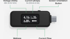
- Add up total measured amperage draw from all other equipment andmultiply by 400 (total amperage × 400 = total BTU per hour at117V). Note that all amperage is figured at approximately 117V. It isbest to use a current measuring device at the power strip inlet tomeasure BTU actual current draw, because nameplate ratings sometimesare fuse size and not what the equipment actually draws.
- Combine BTU/Hr. totals from steps 1 and 2 to obtain total for allequipment. Mark total in column B.
To obtain minimum ventilation requirements:
- Mark ambient room temperature in column C and connect points in Band C with a straight edge.
- The minimum cooling required providing an interior rack temperatureof 85 degrees Fahrenheit is shown on column A, where the straightedgeintersects the minimum cooling requirements column.
System Requirements:
For passive and active ventilation, ensure adequate intake vents areinstalled.
Be certain no short-circuiting of air occurs.
This nomograph assumes full-range rock music is used as programmaterial.
This nomograph assumes that amplifiers are driven to medium-lightclipping levels.
BTU/Hr. Calculations
One hundred percent of the power consumed by communicationsequipment and computer products is converted to heat. CalculatingBTU/Hr. output for equipment other than amplifiers is simple: the morecurrent it draws, the more BTU/Hr. will be produced. At 117V, eachampere of current drawn produces exactly 400 BTU/Hr. of heatoutput.
Amplifiers are not as straightforward because of the differentnature of circuit designs and other variables. The real-world BTU/perhour output can be estimated by taking into consideration which outputdesign is found in the amplifier, the type of power supply, what typeof program material is played, how many ohms the speaker load is, andat what level the amplifier is to be driven on average.


