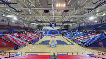
Olympic Dreams: A sound reinforcement system installed at the OlympicStadium in Athens, Greece, highlight advancements in coverage of largeoutdoor spaces.
Nov 1, 1997 12:00 PM,
Jack McLean
The new system, installed on a fast track schedule at the 85,000-pluscapacity outdoor stadium, is based upon a single loudspeaker array.Featuring new loudspeaker design technology combined with complex,specialized signal processing, the new array has been measured to providebroadband uniformity with variation of only plus/minus 2 dB across thesprawling stadium.
Alpha Sound, a sound company based in Athens, provided the system designand installation. Working with acoustician George Papanikolaou, professorin the department of electrical engineering at the University ofThessaloniki in Greece, Alpha chose to implement the first Eastern AcousticWorks (EAW) KF900 series loudspeaker array in a professional installationas the cornerstone of the design.
Alpha Sound had installed the stadium’s original sound reinforcement systembefore the stadium opened in 1980. Horns and compression drivers, mountedon poles at the front of both main seating levels, had been the approach; aVIP seating section receiving supplemented coverage from woofers.
Although the design was fairly successful from a sound reinforcementstandpoint, it had drawbacks. Sight-lines were affected, and members of theaudience would often toss (or attempt to toss) objects into the mouths ofthe horns. In consideration of these drawbacks, along with the advancingage of the system and a push to attract a future Summer Olympic Games toAthens, the call for new system proposals went out. Two proposals offered adistributed concept. Two others, including Alpha Sound’s, were based upon asingle loudspeaker array to be supplemented in shadowed areas by smallloudspeakers mounted under the balcony of the second level.
Stadium officials provided a rating system to guide the proposal process.Aesthetics were clearly of primary importance. Topping the list would bethe location of the loudspeakers and their visibility (or lack thereof).Next came maintenance and accessibility, followed by the sound qualityexpected from both the design and individual components.
The Olympic Stadium can most accurately be described as having a compressedcircular shape. Two seating decks surround the playing surface; the upperdecks have a small break at each end. The surface is larger than normalbecause it must accommodate a full schedule of track and field events,which often happen simultaneously.
The distance across the short axis of the stadium from the back row ofseating on one side to the other is 660 feet (200 m), while the distanceacross the long axis is 890 feet (270 m).
Responding to concernsThe Alpha Sound design, based upon the single loudspeaker array, wasselected by officials. The company also offered other advantages, giventheir long and successful track record with the venue and familiarity withsuch issues as power distribution and existing cable runs.
“We believed that the design we developed would be better because itresponded very well to concerns about aesthetics and sightlines in additionto supplying the sonic performance desired from a new system,” said KostasKonstantinopolulos of Alpha Sound. “Given the extremely tight schedule ofthe project, this also seemed to be the appropriate course to take.”
The start date for implementation was set for late June, shortly after thecontract was awarded. The system needed to be fully functional by the firstday of August, the start date for the world championships. This affordedonly one month for the completion of all fabrication and installation.
Alpha Sound considered two locations for the array – at one end of thestadium’s long axis or at a central point on one of its sides. Ultimately,the choice was the latter option.
“The throw distances would remain relatively constant from the short axispoint, making it easier to attain even full-bandwidth coverage at allpoints,” explained Konstantinopoulos. “And the location we selected alsowould accommodate a support structure to house the array more easily.”
Both the near and far lower level seating areas shadowed by the upper levelwould be covered by 64 EAW compact two-way loudspeakers comprising acompression driver on a conical waveguide providing a 100 degrees coveragepattern. In the nearfield, the portion of the first level beneath thearray, two compact loudspeakers were mounted in tandem, one firing forwardand one firing back. In the far area, only single backfiring loudspeakerswere necessary. Existing cable from the original system made this aspect ofthe system fairly easy to implement.
A large steel structure was constructed for the array, anchored in theground outside of the stadium and running up the outer wall. Rising abovethe upper level rim of the stadium, it elevates the array 80 feet (26 m)above the ground and approximately 15 feet (4.5m) above the rim.
The structure was hoisted into position by a crane and then topped by acustom loudspeaker compartment already loaded with the loudspeakers. Thisapproach made for a much more efficient, not to mention less back breaking,installation of the array.
At the approximate halfway point on the tower, Alpha Sound constructed aweatherproof room to store the system’s power amplifiers and signalprocessing mainframe. The loudspeakers were weatherproofed, and theirstructure was covered by a roof to offer added protection from theelements, particularly intense sunlight. The loudspeakers were also painteda lighter color to deter heat absorption.
Smooth transitionsThe array is comprises five identical columns of EAW KF900 seriesloudspeakers. This was done intentionally to keep the transition betweeneach column as smooth as possible.
The new KF900 Series marks the result of thorough research and developmentby EAW with one primary focus upon the phenomenon of absorption (sometimesreferred to as air loss). Building in part on landmark research documentedby Leo Beranek, the study delved deeply into the true nature and impact ofabsorption, particularly at higher frequencies. At the same time, thecompany revisited the principles of the inverse square law.
Combined with this work was the desire to not only achieve broadband,uniform sound pressure levels at very long distances, but also to tightlycontrol and focus sound throughout the entire listening area. A significantgoal was tight control of sound in the extreme nearfield to eliminate theproblem of intense soundpressure levels that can be both annoying and quitedangerous.
Part of the equation in meeting these criteria is addressed with aproprietary EAW development called Phased PointSource Technology (PPST)that is incorporated in all KF900 series loudspeakers. With PPST, horns anddrivers are placed as close together as possible so that in multiple arraysthey act as either a line array in the vertical plane or as a point sourcein the horizontal plane. Close spacing of the drivers provides the addedbonus of relatively compact enclosure size.
Another part of the equation lies in advanced digital processing, allowingthe coverage pattern to be fine tuned with the vertical axis actually ableto be steered. Thus, control in the horizontal plane is largely achievedwith horn acoustics; in the vertical plane, it’s done largely viaelectronics.
Horizontal coverage in KF900 high-frequency loudspeakers is a hard 30degrees; vertically, the beamwidth is variable and can be tailoreddepending on the DSP adjustments applied. For example, the KF910ultra-long-throw high-frequency module uses the principle of multiplesubsystems, digitally processed to produce the desired results. By itself,each horn in a KF910 is 50 degrees vertically at 2 kHz, narrowing downconsiderably at 8 kHz. However, packing five horns into the cabinet andapplying the digital processing allows attainment of virtually anybeamwidth. Further, the beam is “hot” on-axis and has acontrolled smoothrolloff on the underside. At 60 degrees down, a relatively flat response isachieved.
One array, five columnsThe bottom loudspeaker in each of the five columns of the array is a KF911,which includes two horns on a downward tilt to the main lobe of coverage.These provide the extreme nearfield high-frequency coverage. Next in eachcolumn is a KF910 high-frequency loudspeaker that uses the five horns withcompression drivers and providing long-throw coverage to the far side ofthe stadium.
Processing is heavily implemented for seamless vertical transition from theKF911s to the KF910s. This transition occurs at the playing surface ratherthan in any seating area, rendering it less perceptible to the audience.Above the high-frequency devices in each column is a single KF920mid-frequency loudspeaker with three 10-inch loaded horns. Topping eachcolumn are two KF930 low-frequency loudspeakers, each loaded with four15-inch woofers.
Because the KF series is so new, existing modeling programs have yet to beupgraded to supply accurate predictions of key performance parameters. As aresult, Alpha Sound relied upon a proprietary program devised by EAW seniorengineer David Gunness to produce an accurate model of coverage produced bythe array. This data was then mapped onto architectural drawings of thestadium, resulting in information that guided signal processing parameters.Further, the modeling showed the uniformity of coverage that could beattained, along with aspects such as frequency response and maximum outputlevels.
Coverage by both area and seating level is somewhat variable. One of theinherent advantages of the KF900 Series is that the exact vertical patternof any one of the columns is determined largely with the signal processing.This changes from column to column with respect to the different geometriesthat each column is required to cover.
Obviously, a significant amount of processing horsepower is required forthe KF900 series. The Peavey MediaMatrix digital processor offers enoughcapability in the static environment of a fixed installation.
Within a KF900 series system, the requirement is that each verticallyaligned cell (horn and driver combo or woofer) has its own specific time,phase and frequency processing parameters. Thus, in the Olympic Stadiumarray, each of the seven high-frequency cells in vertical alignment in eachcolumn has its own processing, as do each of the three mid-frequency cellsand four low-frequency cells of each column.
Again, with this project, the columns are symmetric with respect to thecenter line of the array. As a result, the center column is on one set ofprocessing, while the two inner columns also have identical parameters, asdo the two outer columns. This symmetry-induced efficiency offered anotherbenefit: Drivers could be doubled up on the same amplifier channel, therebyreducing the total number of channels needed to drive the array.
Each column, then, has 14 total channels of processing. Multiplied by threedifferent configurations required for the five columns, and the total runsto 42 channels of processing needed for the array. It equals a whole lot ofprocessing horsepower contained within one chassis, the primary reason forthe selection of MediaMatrix.
“Having 42 channels of processing supplied maximum flexibility in settingup and fine tuning the system,” explains Gunness, who was on hand to assistwith system implementation. “Because this was the first installation of aKF900-based system, the flexibility was a great luxury. We also learnedsome things along the way that will allow us to be even more efficient inthe future with respect to the processing.”
The loudspeakers are essentially stacked on top of each other within thestructure in addition to being hard packed with their sides together. Thisis consistent with the KF900 series design philosophy in which thehigh-frequency drivers in particular are intended to be very close to eachother, helping to provide smooth lateral transitions.
There is no downward tilt of the array; it actually fires above the lastrow of seating on the opposite side. All of the “tilt” of energy downwardis done via the downfill loudspeakers and the processing, which steers theselected coverage patterns down while allowing the array to retain itsnecessary point of axis.
Processing and power elementsSeveral types of processing were implemented within the cluster via theMediaMatrix DSP mainframe. However, because the system is fixed within thevenue and is intended to meet speech intelligibility requirements, there isno real-time type of control included in the package.
>From a pure frequency standpoint, there is pre-emphasis to project highfrequencies at the longer distances, combating normal air losses. The otheressential processing element is time, both in terms of delay and phasealignment. This helps adjust the sound lobe, tilting it where it’s supposedto fire and also helping to retain constant directivity over its operatingbandwidth. This processing is largely achieved by a number of digitaldelays with approximate 20 ms resolution along with the use of filters andtheir phase characteristics to help align the cluster cells.
Once all filter and delay characteristics were determined, along withfacets like appropriate gain structures and limiting, the processor wasset. Following “tweaking” done during system commissioning, it has remaineduntouched and will likely remain so for the foreseeable future.
Crest CKS series power amplifiers, located in the tower to minimize cableruns, drive the mid- and high-frequency components within the array;beefier Crest 9001s power the low-frequency loudspeakers. Crest CKVamplifiers on 70 V lines are at the control position power the distributedunderbalcony loudspeakers. All of the amplifiers are on a Crest NexSyscontrol bus that facilitates remote load monitoring from a personalcomputer at the control position.
A new Mackie console was also installed at this location. With 24 inputsand four buses, it provides plenty of capability for the limited range ofprogramming hosted at the venue.
More than intelligibility>From a sound reinforcement standpoint, the absolute critical goal for thenew system was speech intelligibility. At the world track and fieldchampionships, for example, Konstan-tinopoulos points out that “the resultsof events are not official until they’re announced. This demonstrates justhow important it is to clearly hear the spoken word.”
Measurements are still being gathered regarding overall performance of thesystem. In addition to the documented plus/minus 2 dB variation withbroadband uniformity throughout the stadium, music levels at the VIPsection have been measured at 10 5dB.
“Levels of 108 dB to 110 dB, consistent through the venue, are the goal. Webelieve that this is easily within reach,” he concludes. “In addition,frequency response measurements during the setup phase of the projectshowed a flat response, within 2 dB, to 5 kHz at the farthest seats fromthe array, with a gentle rolloff at frequencies above that.”