Playing The Right Cards: Understanding how constant-voltage distributedloudspeakers work will help your next project run more smoothly.
Jan 1, 1998 12:00 PM,
Pat Brown
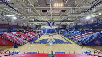
When it comes to sound coverage, casinos have much in common withfactories, cafeterias and department stores: Intelligible sound must bedelivered to a large area. The ideal way to accomplish this might be with asingle, very powerful loudspeaker. Such a system would be simple, easy toinstall and require only one power amplifier. In real-life, such anapproach might have some severe drawbacks. First, all listeners would haveto be roughly the same distance from the loudspeaker. This would requireplacing the loudspeaker a great distance from the audience, which for largespaces might pose a problem for low-flying aircraft. If this approach isnot practical, the single loudspeaker could be replaced with multipleloudspeakers, each covering a smaller unit area. This is the essence of adistributed loudspeaker system. If the listener needs a direct field soundlevel of 80 dBA to provide clear speech above the room’s ambient noise, itreally doesn’t matter if it comes from a device at a remote distance (largedistance, high power and/or directivity) or from a device in closeproximity (short distance, low power and/or directivity). Both approachescertainly have their tradeoffs. Assuming that the design variables fall infavor of the latter approach, several obstacles must be overcome for thesystem to work properly. First, you must deal with problems in coverage.Because many loudspeakers are being used, the resultant acoustical chaosmight reduce the clarity of the system. Also, in a reverberant space (onewith a long persistence of sound energy), the reverberant energy (soundafter many reflections) may build and become a noise source in and ofitself. The second problem is power distribution. If many loudspeakers wereconnected in parallel, the load presented to the amplifier would be low.This low load would effectively short the amplifier (they don’t like that),reduce the damping factor (ratio of load impedance to amplifier outputimpedance) and result in excessive power losses in the loudspeaker wiring.In short, it will run hot and sound terrible.
It is the job of the sound-system designer to address these problems andprovide the client with a workable design. Let’s take them in order.
CoverageThe best means of communication is a single source and single listener inclose proximity. A good example is face-to-face conversation. This assures(at least in non-hostile acoustical environments) a positivedirect-to-reverberant sound ratio and a positive signal-to-noise (roomnoise in this case) ratio. We are all pretty good at adjusting until theseconditions are met, either consciously or subconsciously. In practice, asound system must provide better than face-to-face communication conditionsbecause gestures, inflections and lip-reading are not involved in thecommunication process. A successful distributed loudspeaker system mustmeet these criteria.
This is where the tradeoffs begin. If the number of loudspeakers isincreased so as to cover all seating positions, the reverberant energy inthe room will increase. If it increases to the point where its level is thesame as the direct sound field (referred to by designers as criticaldistance) the reverberant energy can dominate and reduce speechintelligibility. The designer must therefore predict the level of thedirect sound field and the level of the reverberant sound field. These arecalled LD and LR, respectively. LD is determined by the emitted acousticpower, LW, the directivity of the loudspeaker, Q, and the distance from theloudspeaker, DX. In turn, LR is determined by the emitted acoustic power,LW, the absorption in the room, Sa, and a multiplier that accounts for theadditional loudspeakers that are driving the room, N. When these parametersare quantified, the ratio of LD to LR can be evaluated to determine if thesystem will work properly. In general, the principles are that manyloudspeakers (high N) require short listening distances, and vice versa;that the room’s acoustic parameters (reverberation time, background noiselevel) will limit the maximum listening distance for acceptableintelligibility; and that room treatment can be required if the requiredlistening distance becomes too small (lower than the ceiling height).
In short, if I place a loudspeaker into the room, I need to know how muchof the energy actually delivers information to the listener and how much ofit only serves to aggravate the situation. I can give you a clue: The vastmajority of the emitted energy is working against us and not for us.
Another danger of distributed systems is that delayed sound from remoteloudspeakers may reduce the clarity of speech. Time offsets of more than 50ms begin to cause problems, and the longer the time offset, the worse theproblem becomes. Care must be taken to aim loudspeakers in such a way thatthey don’t produce high levels at other listening locations in the space.This requirement usually means aiming them straight down toward the floor,which reduces the coverage area, requiring more total loudspeakers.
The actual number of loudspeakers required is determined by the size of theaudience, the height of the ceiling and the coverage angle of theloudspeaker.
The area covered by a single loudspeaker can be found by the followingequations:
r = (h – 1) tan(a/2)
A = pr2
where r is the radius of the covered area, h is the ceiling height, l isthe listener height, a is the loudspeaker coverage angle, and A is the areacovered by a single loudspeaker. The required number of loudspeakers forhigh-density coverage can be found by this equation:
# of loudspeakers = coverage area/r2
This will yield roughly the same number of loudspeakers as lightingfixtures in most spaces. You will probably have to compromise. Divide bytwo for minimum-overlap coverage, and divide that by two for edge-to-edgecoverage. Proven design equations also exist that allow these parameters tobe examined (which unfortunately would require another article).
Power distributionAt some point in every sound system, the electrical output of the poweramplifier must be coupled to the loudspeaker voice coil. The most common,simplest and best connection is a length of wire of adequate gauge to allowthat a signal loss (caused by the wire’s resistance) of no more than 0.5dB. Such a change in delivered power would be inaudible in all but the mostcontrolled listening environments. With long lines, direct voice coilconnection becomes impractical because the wire gauge required is toolarge. Enter high-voltage distribution.
This process, borrowed from the companies that provide us AC power in ourhomes, allows the amplifier output to be coupled to the loudspeaker withsmaller cable than would be otherwise necessary. Hoover Dam serves as anice example of how this is accomplished. Once generated by thewater-driven rotating turbines, the electrical energy (which consists ofvoltage and current) must go long distances before it is used. High-voltagedistribution is one way to accomplish this task. A quick primer is in order.
Electrical power is made up of two components: voltage and current.Consider your garden hose. The voltage component is analogous to the waterpressure, which makes the water move through the hose when a faucet isopened. The current component is analogous to the flow of water, and theload (impedance) can be thought of as the opposition to the flow of water,which in this case might be the diameter of the hose and whatever widget isaffixed to where the water comes out (sprinkler or nozzle). All of thesecombine to allow energy (or water) to get from one place to another. Thelower the opposition to electrical current (impedance) the more the currentthat will flow, as long as there is sufficient voltage (pressure). Ingeneral, in a conductor (or water hose), the lower the impedance(opposition, which for wire is primarily in the form of resistance), thegreater the current (flow), and the lower the voltage (pressure). Somequality time spent with a water hose and a well-placed thumb will serve toillustrate these principles. Conversely, the higher the resistance, thelower the current and the higher the voltage. Moving energy from one placeto another can be accomplished with high voltage and low current, or lowvoltage and high current. Let’s look at Ohm’s law:
W = I x E
where W is power in watts, I is current in amperes, and E is voltage in volts.
Ohm’s law proves that whatever the case, the same amount of energy flow cantake place. The signal processing chain ahead of the power amplifieressentially passes voltages from one device to the next with little needfor significant current. As such, electronic device input impedances arealways high, allowing maximum voltage (pressure) to develop. The voice coilof a loudspeaker likes to see a substantial amount of current flowingthrough it because the desired result is the motion of the loudspeakerdiaphragm. A low voice coil impedance guarantees this. Consider thecoupling of the output of a 100 W power amplifier to a loudspeaker. Aloudspeaker impedance of 8 V means that the power amplifier must produceabout 28 V across it allow the 100 W to be delivered to the loudspeaker.Because only 100 W are available, a higher voltage from this amplifieracross this load would not increase the power. Neither would a lowerimpedance loudspeaker with 28 V across it. They are called power amplifiersfor a reason. It is the combined voltage and current available from anamplifier that is of interest. We can now consider the various ways thatthis 100 W can be delivered to the loudspeaker.
The first is to keep the voice coil impedance at 8 V. The advantage of thismethod is that it is simple and sonically accurate. The disadvantage isthat if the cable run becomes too long, the resistance of the wire itselfwill dissipate some of the energy that was meant for the loudspeaker. Asstated earlier, an acceptable line loss of one-half of one dB is prettystandard, which means that the loss will not be audible to the listener(and your wires won’t get hot). The longer the line, the heavier the wirethat must be used because the resistance of the wire is inverselyproportional to its cross-sectional area (just as a larger water pipeallows more water to flow). As the line length grows, at some point therequired wire size gets too big to be practical (no one enjoys stringingbattery cable through attics); other methods must be considered.
One option is to use a step-up transformer at the output of the poweramplifier. Because the power into and out of a transformer is the same(assuming no significant loss in the transformer, which never happens butis fun to think about), a low voltage and high current presented to theprimary side will be transformed into a high voltage low current on thesecondary side. (Remember Hoover Dam?) In effect, the voltage from theamplifier has been increased, and the current has been proportionallydecreased, but the power has stayed the same. When a transformer steps upthe voltage, it also steps up the impedance. As the impedance increases,the resistance in the wire becomes less significant. Figure 1 (from theSyn-Aud-Con Sound System Calculator) shows the values of voltage andimpedance that result in 100 W of dissipated power.
If it is not practical to distribute the power at 8 V, simply move right onthe chart and step up the voltage and impedance to a higher value.
Applying some numbers, a 0.5 dB acceptable loss would require that the wireresistance not exceed about 5% of the loudspeaker load. For an 8 Vloudspeaker, this would be about 0.4 V. Figure 2 shows the resistance of100 feet (30.5 m) of wire as a function of wire gauge. The required gaugein this example, rounding to the next larger size, becomes AWG#12.
Using transformers to step the amplifier’s output voltage up to 70.7 V atthe amplifier end and back down to 28 V at the loudspeaker, the impedanceof the loudspeaker line now becomes 50 V, and the acceptable resistance ofthe wire (at 5% of load) is 2.5 V. Figure 2 shows that we could transversethe 100 feet (30.5 m) with 20 gauge wire and still lose only 0.5 dB. Theprice paid is the cost of the transformer, the inherent insertion loss (younever get something for nothing in audio) and the reduction of soundquality that can result from using cheap transformers (buy the good stuff).At the other end of the line, we still have an 8 V loudspeaker to which weare trying to deliver this energy. If it were placed directly across the 70V line, it would demand more current than the power amplifier is capable ofdelivering because of the increased operating voltage of the line. (SeeFigure 3.) So a second transformer is needed to “undo” what the first onedid. It will be used to step down the voltage and impedance to theiroriginal values that existed at the output of the power amplifier. What hasbeen accomplished is that the 100 W has been delivered to the loudspeakerusing much smaller wire than would have been necessary without thetransformers. If done properly, neither the amplifier nor loudspeaker willhave any idea that you went to all of this trouble to deliver the requiredpower (ignorance is bliss).
Some other options exist from using this means of power distribution. Weknow that 100 W is available to the line (the amplifier size), but who saysthat we must deliver it all to a single loudspeaker? If only 10 W wereneeded at the loudspeaker, an appropriate step down transformer could bechosen to accomplish this. There would then remain 90 W of amplifier poweravailable for use elsewhere. In fact, the amplifier doesn’t know if its 100W is going to one loudspeaker or many loudspeakers. All it knows about theoutside world is the impedance that is presented to its output terminals.(It’s a little like paying taxes. You don’t really know where it went; youjust know that its gone.)
A good example of this type of power distribution is the electrical wiringin your house. (See Figure 4.) On a given circuit, there is approximately110 V present at each electrical outlet. (Unfortunately, voltage has beenknown to be anywhere between 110 V and 120 V in standard Amrical outlets.)All devices designed to plug into a wall outlet operate at this voltage(even though internally they might convert it into a larger or smallervalue). Even though they operate at the same voltage, they do not draw thesame power. Devices that do a lot of work (toasters, hair dryers, heaters)will draw much current and therefore consume significant power. Devicesthat don’t do a lot of work, such as radios and cassette decks, requireonly a small amount of current and consume little power. Any combination ofthe above can be plugged into the circuit, as long as the total powerconsumed does not exceed the power available. For a standard householdcircuit, this will be about 2,400 W (120 V at 20 A). We might call such acircuit a constant voltage circuit, since the voltage is always 120 V. Theonly difference between this and audio systems is that in an audio systemthe voltage is fluctuating in amplitude in relation to the audio signal, soconstant voltage circuits are only at their maximum voltage (i.e., 70 V)when the program material is at maximum level.
It is the value of the line voltage and the impedance presented to the lineby the loudspeaker/transformer that determines the power delivered to theloudspeaker. If the voltage is standardized, it is possible (and commonpractice) to label the taps on the loudspeaker transformers in watts ratherthan ohms. This makes the transformer choice quite simple. Just select onewith a wattage rating that delivers the required power to the loudspeaker. Of course, once labeled watts, the values stamped on the transformer are true only if the specified line voltage is available. We will address this issueshortly.
There is nothing sacred about 70 V when it comes to high-voltagedistribution. It is simply the most-commonly used distribution voltage.Other distribution voltages can be used. The actual choice is often basedon the available equipment and the local electrical codes. The followingexamples use 70 V, but the principles are the same for all distributionvoltages (only the numbers change).
Setting up the 70 V lineGood gain structure practice necessitates proper adjustment of theamplifier. Here are some things to remember about 70 volt lines:
70.7 V is the maximum RMS voltage that is available to the line. There willrarely actually be 70 V present on the line. Because the audio signal isdynamically changing (we don’t play sine waves to audiences), the 70 Vlimit means that only the peaks in the program material ever reach 70 Vrms,and we will operate at a much lower average voltage to maintain someheadroom (headroom is the distance between your dog and the flower bed whenyou set the length of his chain). Using some easy numbers, 6 dB of headroomwould mean that the actual average voltage of the line would be more on theorder of 35 V. Keep this in mind when choosing transformers. The powerrating of the transformer represents the maximum power that will bedelivered. The average operating power will be lower for program material(stuff that you would want to hear coming out of a sound system).
70 V lines should be 70 V lines. Operating the line below its rated voltagewill result in improper transformer choices for future system expansion.For instance, if your calculations indicate that a 1 W transformer willsuffice to deliver the needed level to the listener, but the 70 V line onwhich it is to be installed is only running at 10 V, you will be scramblingfor a larger transformer after installing the loudspeaker. Good gainstructure practice is to calibrate the system so that clipping occurssimultaneously in all components, including the power amplifier. In thecase of high-voltage distribution, amplifier headroom is realized byadditional available current (and hence, power), not additional voltageoutput of the power amplifier. A 300 W power amplifier should be producing70 V for peaks in the program material, even if the combined taps of alltransformers only allow 100 W to be drawn from the amplifier. Again, excessamplifier power in this case means that we can place many more loudspeakerson the line without exceeding the current producing capabilities of theamplifier.
The most common problem with 70 V lines is failure to provide theappropriate impedance to the amplifier. This results when either too manyloudspeakers are placed on the line or a loudspeaker without an appropriatetransformer is placed on the line. In either case, a quick impedancemeasurement of the loudspeaker line will identify most potential problemsprior to powering up the amplifier.
With all of this in mind, the “tools of the trade” for installing andtroubleshooting distributed loudspeaker systems are an impedance meter,used to measure the load presented to the amplifier; a voltmeter, used toestablish the operating voltage of the line; polarity testers, used to makesure that all loudspeakers are in polarity (push and pull together), and asound level meter, used to check the resultant coverage of the system.
A good high-voltage distributed loudspeaker system begins with a gooddesign, performed by an individual who understands the tradeoffs betweensystem parameters and sound levels. Even a good design can sound bad if itis not installed and calibrated properly. Proper installation requires atrained technician who can measure voltage, impedance, polarity and soundlevel. When designed and installed properly, distributed systems canprovide a wonderful listening experience.