The RF Way
Jul 1, 2002 12:00 PM,
Gordon Moore
There’s no question cable is best at moving audio when signal integrity is critical; but occasions do arise in which labor, time or space make a hardwire system more of a hindrance than a help. A historical building may be protected, for example, but the owner needs to get audio from one end to the other. A parade might need common audio on the floats mixed from a fixed location, but can’t have cables running to the floats for obvious reasons. Perhaps a large-venue concert risks having too many cables getting stomped into the mud. In situations like this, when cabling isn’t an option, we have to look at other methods of moving audio signal.
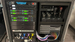
One creative solution is a radio frequency link. The RF link can be provided in many ways, but for the systems integrator some are difficult to implement. The lowly wireless microphone and its cousin, the in-ear monitor system, have sometimes been pressed into duties not originally envisioned for them. Low-powered RF links like those are occasionally used because of their convenience and affordability. But when a RF link has to go beyond amplifying individual lecturers or performers — when a mixed audio signal, typically at line level, needs to get to another audio component — then a more sophisticated RF link is in order. One example is a system in a piano bar in which a small mixer carries mixed audio from piano mics and performer mics to an amplifier rack across the room. Another example would be a mixer whose output is carried to several delay stacks at a live performance (without cables on the ground).
- Output Power Level. Several factors must be considered when choosing equipment for this sort of application. The first factor is transmitter output power level. Wireless microphone transmitters vary wildly in their rated output. Some models will have 1 mW or less, and others may range from 10-20 mW. High-end systems can offer as much as 250 mW (a quarter watt). Naturally, a higher output power means greater range, but even at close range, the transmitter output power can significantly affect the performance of a system.We live in an RF intensive world, and it’s getting busier all the time. Ten years ago, cell phones were the tools of the rich and elite. Now, they’re everywhere. A decade ago, digital television was only a gleam in the eyes of a few visionaries. Now it occupies more than 100 MHz of spectrum space in many areas of the country. Cordless phones, wireless modems, wireless Internet — wireless everything — means the spectrum is getting busier. As a result, even a wireless microphone operating in a clear spectrum is susceptible to interference from third order or higher intermodulation (that is, unplanned radio frequencies that result from the interactions of multiple radio frequencies). Many of these interfering radio signals are fairly weak, but if the radio signal you are using is also weak, then the possibility of the weak interference causing problems is greater.Given a choice between 1 mW and 100 mW (a 20 dB difference), it makes sense to go with the higher output power to keep better signal integrity. The FM discriminator circuit in a wireless receiver generally needs about a 10 dB difference between the wanted signal and the interfering signal to bury the interference in the noise floor of the receiver. If you can use a transmitter with higher power, opt for the greater output.
- Receiver Selectivity and Sensitivity. After transmitter power, consider receiver selectivity, the receiver’s ability to reject near frequency interference. Check the third order intercept figure in the receiver specifications. A good number would be -15 dBm; a better number would be +1 dBm or higher. If this figure is not in the specification sheet, call the manufacturer for the rating before you consider using the receiver as an RF link.Because the applications being discussed need good signal reliability, the receiver should have good sensitivity to keep the signal locked in. This spec refers to the RF signal level required to provide a good signal-to-noise ratio in the audio signal. The most common ratings are either expressed in SNR or in SINAD (Signal + Noise + Distortion divided by Noise + Distortion). A good figure would be 1 uV for 20 dB SINAD, and better would be 0.5 uV for 20 dB SINAD. (SINAD is considered more accurate than SNR for wireless.)
- Signal Level. The transmitter will need to be able to accept the correct level signal from your source. The source could very well be a line-level signal, but many transmitters are not set up to deal with line levels, so you may have to pad down your signal source or specify a wireless transmitter that can use line levels. The signal should not overload the input of the transmitter or it will clip. You can use an inline attenuator to reduce level ahead of the transmitter input.
- Frequency. Careful frequency analysis and coordination is essential. If you are going to have a reliable link, the frequency selected needs to be free of interference. If possible, monitor the frequency you propose using at the same times of day as you would expect the RF link to be in operation, especially if the distances between components will push the limits of the system. If more than one channel is involved, get assistance from the manufacturer in selecting compatible frequencies.
- Power. Finally, for a reliable RF link, you will have to provide a steady source of power to the transmitter. Because this system will be acting in place of a cable, it will need an on-demand power source whenever the system is operating. That means replacing the battery with a battery eliminator, a dummy battery connected to an outside power supply that provides the proper voltage for the transmitter. More advanced units will have onboard regulators to allow for variances in the voltage provided from the outside source. Use a good transformer to step down the operating voltage to avoid the possibility of setting a ground loop between your transmitter and other components in the system.
EXAMPLE 1: THE BAG SYSTEM
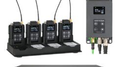
the “bag system” originated in the broadcast industry. Sound mixers for news magazine shows such as 60 Minutes and Dateline often use the system. Two cameras are used during an interview: One camera is trained on the talent, the other on the interview subject. Both the interviewer and the subject wear wireless microphones; the signal from each microphone is picked up by two receivers carried in shoulder bags. The audio from each receiver is fed to a portable mixer also carried in the bags. The sound operator mixes the two mics into a blended stereo audio signal, sometimes adding a boom mic for ambient background.
This live mixed stereo signal is then sent from the mixer to two more transmitters in the bags. Those are the RF links that free the camera operators from any cabling. The system allows both cameras to capture a real-time mixed stereo signal while freeing the camera operator of movement restrictions and concerns about getting the audio. The camera operators can then concentrate on the visual side while the sound mixer concentrates on audio. Post-production costs drop because the audio has already been mixed for the interview footage. As the video is edited, the audio follows along.
EXAMPLE 2: THE BIG CONCERT
the second example comes from a Fourth of July tradition in Maryland. Every year, the Maryland Symphony Orchestra assembles at the Antietam Battlefield near Sharpsburg, Maryland, for a concert on the battlefield grounds (complete with howitzers). Attendance had swelled to the point that more than ten delay towers were required to get the audio evenly distributed over the battlefield to the 40,000-plus people in attendance. Mike Sokol of ModernRecording.com was asked by the concert organizers to find a more efficient way to get the audio to the speakers. At the time, miles of balanced audio cable had to be run over potentially muddy ground. Sokol pointed out that so much wire would pick up every extraneous EMF field in the area and increase the possibility of a serious ground loop problem. There was an additional hazard from lightning, and the system had to be set up two days before the concert. One ground strike after all the cables were down could destroy ten towers of gear.
What the system needed was a dependable RF link to each tower. The towers each needed their own RF receivers feeding the audio to a digital delay, equalizer, amplifiers and speakers. Driven by individual generators, each tower would be entirely self sufficient and electronically isolated. Sokol selected Lectrosonics UDR200 receivers for their high sensitivity — the signal had to go from the mixing console to delay towers more than 1000 feet away. The tracking front end, which retunes the radio RF front ends as the frequency is changed, assured good interference rejection. Sokol also addressed the switching power supply. The towers supported large amplifiers running on 220V power. The switching power supply of the receiver automatically adjusted to the higher voltage without special changes.
Audio from the stage microphones was mixed at the FOH console, then sent to a 250 mW UM250 transmitter. (The transmitter has a line level input pin, so the line level signal from the mixer presented no problem.) To improve transmission, Sokol elevated the transmitter on a 15-foot boom. Doing so raised the transmitter above the crowd and the console, making for a clear signal path to the receivers at each stack. A redundant transmitter was rigged as well, but with the power off to avoid signal jamming.
- Victory! July 4, 2002, was the sixth time the entire concert was carried on the back of a 250 mW transmitter. The primary transmitter has never failed. The one year the show staff lost the pilot tone circuit on one receiver, they threw the pilot tone override switch and had the tower back up and running. Sokol said that the audio is better because there were no long line-cable losses, and that they have stopped using special ground-plane antennas, going back to the stock rubber-duck style antennas on the receivers. He admitted to a great deal of nervousness the first year. “Once we went RF link, there was no looking back,” Sokol said. Setup time is quicker, tear-down is easy (no gathering up miles of cable), and the trip hazard is no more.
EXAMPLE 3: RF PARADE
a well-known theme park used 16 UHF systems for a parade, which needed a reliable source of audio for the floats. Naturally, float motion prohibits the use of cabling.
According to Uwe Sattler, technical director of Sennheiser USA, the parade system is configured as four subsystems with four transmitters each. “The systems [can] be ganged, if necessary, as one or more standalone 4-, 8-, 12- or 16-channel systems through one or two common antennae,” Sattler said. “It consists of sixteen 250 mW UHF transmitters, eight operating between 764 and 770 MHz and the other eight between 782 and 788 MHz. Four RF outputs of each range are combined through custom antenna combiners with a minimum isolation between all input ports of greater than 30 dB and maximum attenuation of less than 2 dB from input to output. The two tuned combiners for each range are added through tuned stubs, and the summed signals are fed to two custom, bottom-fed, collinear antennae with more than 8 dB gain and 4-6 degree downtilt of their radiation pattern with a ±15 degree beam width.”
The antennae combiners allow the multiple transmitters to broadcast the audio through a pair of antennas, eliminating a forest of separate antennas. In theme parks, the objective is to lead visitors into the illusion of escaping the everyday world. Maintaining a clean appearance without the intrusion of a technological antenna array is very important. The antenna tilt Sattler describes helps maintain even coverage of the parade route without spillover outside the park.
Sattler also points out that a permanent installation such as this one places the wireless transmitters outside the normal venue of the Part 74 license for wireless microphones because the transmitters are fixed. That violates the intent of the regulations governing wireless microphones that are, essentially, mobile systems. To keep the system and its owners clear with the FCC, a special license was garnered to allow this installation full legal operational status. Sattler emphasizes that any application in which the transmitters are permanently installed will have to have the licensing issue settled before going on the air. The FCC is concerned not only with proper frequency allocation but also the transmitter coverage to assure the wireless does not improperly interfere with other areas or equipment.
POSSIBILITIES APLENTY
in one house of worship, getting cables from the mixing desk back to a cry room was cost prohibitive. An in-ear monitor system was used as an RF link, which helped get stereo audio without the burden of running cables through the historic structure. Because the volume of the powered speakers in the cry room were easy to set by the attendants in the room, the mixing desk could concentrate on the signals in the main sanctuary without worrying about affecting levels in the cry room.
RF links through wireless microphones can be reliable and offer superior audio quality. They must be carefully planned, tested and backed up, however, especially in critical applications. If you do the proper homework and pay attention to all the details (including FCC licensing restrictions), you can create a working system that reduces labor, time and even cost.
Gordon Moore is the vice president of sales for Lectrosonics Inc. and was selected as Educator of the Year for 2000 by ICIA. He can be reached at [email protected].


