The ABCs of ATSC
Digital terrestrial TV offers so much more than analog TV that you should expect more clients to add it to new and retrofit installations. DTV means multicasting, support for multiple language channels, audio description and closed captions, HDTV and SDTV, and electronic program guide information. What’s it take to achieve? Here’s an overview of the ATSC system.
As I walked the aisles of Infocomm last June, I couldn’t help but notice how much the show is starting to look like the National Association of Broadcasters Show, particularly with companies like Harris, Thomson Grass Valley, Sencore, and Tandberg exhibiting. Add in a shift towards Internet Protocol and fiber-optic backbones, toss in digital media servers and MPEG encoders, and you can see where our industry is heading.DIGITAL VS. ANALOGSOMETHING OLD, SOMETHING NEWWhat’s interesting about the ATSC modulation system is that it actually recycles part of the NTSC TV system. As I mentioned above, NTSC depends on amplitude modulation (AM), or varying the signal strength of the video carrier. In an AM signal, 50 percent of the energy is located in the upper and lower sidebands that surround the carrier, and these sidebands contain the same information.Upper and lower sidebands contain the same information for redundancy. In 8VSB, the lower sideband and most of the carrier frequency are filtered out, leaving a tightly filtered upper sideband (USB) signal that fits into a 6-MHz TV channel (see Figure 2).
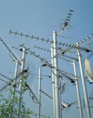
Credit: Photo: Klaus Hackenberg/Zefa/Corbis
One thing the pro AV channel hasn’t focused on much, though, is radio frequency, however I noticed a few companies showing combo ATSC (digital terrestrial) TV receivers and flat-panel HDTVs for professional installation. (ATSC stands for Advanced Television Systems Committee.) The fact is, digital terrestrial TV offers so much more than analog TV that I would expect more clients to add it to new and retrofit installations, particularly in the primary and secondary education markets. DTV means multicasting, support for multiple language channels, audio description and closed captions, HDTV and SDTV, and ancillary data including electronic program guide (EPG) information.
Moreover, digital terrestrial TV is free to receive and offers superior image quality and bit rates. And in the post-Sept. 11 age, there have been more requests for over-the-air reception of TV signals in the event other carriers, namely digital broadcast satellite and cable, are interrupted. Already, companies such as LG Electronics make extensive use of the digital data overlay created for the ATSC system–called Program and System Information Protocol, or PSIP–as part of their digital signage backbones through subsidiary Triveni Digital. Variations of the modulation system (known as vestigial sideband) are being demonstrated for handheld and mobile applications. And some public safety officials have advocated for ATSC reception as a backup to cable and satellite communications in case of emergencies.
As much as the conversion to ATSC and DTV next year is characterized by consumer undertones, its application will be far-reaching. And judging by attendance at an InfoComm Super Tuesday session I taught with Lectrosonics’ Gordon Moore, AV pros have more than a passing curiosity in the technology.
Had other things to do at InfoComm? No problem. Here’s an overview of the ATSC system.
There are plenty of good reasons to adopt a digital TV system instead of analog, but the most compelling is that digital breaks the link between signal strength and image/audio quality. In the NTSC analog TV system, picture quality is directly related to the amplitude of the video carrier, described as carrier-to-noise ratio, or C/N. The stronger the carrier, the cleaner the picture. The problem with this system is that changes in amplitude can degrade picture quality. Worse, changes in phase aggravate the problem and can render video unwatchable. Ghosts, noise, and phase errors all add up in a hurry.
In contrast, digital TV has a much lower acceptable signal threshold. In a perfect (Gaussian) environment, that threshold is specified at 15.3 dB C/N. (An NTSC signal with that low a carrier-to-noise level would be all noise.) In a real-world (Rayleigh) environment with multipath and interference issues, the usable level is somewhat higher–about 20 to 22 dB C/N. Multipath means radio signals reach the receiving antenna by two or more paths.
But that’s still 10 dB lower than the 32 dB C/N cable TV specification for DTV signals entering a house (quadrature amplitude modulation, or QAM), And analog CATV signals are typically much stronger (about 10 to 12 dB higher than QAM carriers).
With digital, all that matters is that the bit stream is received continuously and that there’s forward error correction (FEC) built-in so that dropped data can still be recovered, ensuring clean pictures and hit-free audio. Given the pernicious nature of over-the-air signal propagation, any TV system that eliminates phase errors and noise, and that can handle moderate to strong multipath, should be very attractive for next-generation broadcasting.
an RF spectrum analyzer.”/>
ATSC digital TV channels WNYW-44 and WABC-45 from New York City, as viewed on
an RF spectrum analyzer.
Credit: Photo: Courtesy Pete Putman
In the 1950s, Collins Radio developed a new communication system called single sideband (SSB) that made full use of this phenomenon. The AM carrier was filtered out, along with one of the two sidebands, making for a more efficient way to communicate that didn’t actually transmit any energy until modulated. Fast-forward 50 years to a similar trick. In the ATSC system, the lower sideband energy and carrier frequency are filtered out, leaving us with the upper sideband, a vestigial sideband or VSB for short. And the energy in that sideband is equalized across a 6 MHz TV channel.
ATSC is standardized around MPEG-2 compression for digital video and Dolby Digital AC-3 encoding for audio. MPEG packets can travel over any connection, including serial digital video, Cat-5 wire, and fiber optics. In the ATSC system, the serial digital video stream is standardized as SMPTE-310.
Now, how are the signals broadcast?
STEP BY STEP
In the ATSC system, an eight-level vestigial sideband (8VSB) modulation system is employed for broadcast television with a maximum data rate of 19.39 megabits per second in a standard TV channel. (Yes, some of the system is backwards compatible.)
Encoding an 8VSB signal for broadcast follows these steps (the steps are reversed for signal reception):
- Frame synchronization: MPEG-2 packet strings are always 188 bytes long, with the first byte used as a sync byte. A frame synchronizer looks for that sync byte to find the starting point for a packet (video, audio, or data). Later on in the process, the sync byte is replaced with frame sync.
- Data randomization: To even out the spectral energy of the data bursts, byte values are randomized using common random number generation algorithms. This process is what results in the characteristic flat-top shape of an 8VSB carrier and allows use of the entire 6 MHz channel with minimal adjacent-channel interference.
- Reed-Solomon coding for forward error correction: In this step, an image is created of each packet that consists of 20 parity bytes. It’s appended to the end of each DTV packet and is used by the 8VSB receiver to look for dropped or corrupted bytes as each packet string is received. The maximum number of byte errors per packet is 10. Beyond that, data is not recoverable and video/audio dropout occurs.
- Data interleaving: This step further randomizes bytes among many DTV packets. These new packets retain the 207-byte length (187 bytes plus Reed-Solomon FEC bytes). Data interleaving ensures that only small parts of the original packets can be lost or corrupted during transmission, and a standard mathematical pattern is used by the receiver to recover and unscramble interleaved packets.
- Trellis coding: This is another version of forward error correction that convolves each 8-bit byte of data to four 2-bit words. The transition from one 2-bit word to the next is expressed as a 3-bit binary code (23 = 2 x 2 x 2 = 8 levels). You’ve probably already guessed that this is where the “8” in 8VSB comes from. There are also 2-bit (4VSB) and 4-bit (16VSB) variations for specialized applications.
- Sync insertion: At this point, four symbols are added at the head of every data segment and are known as segment sync. A tri-level pulse is used to create the transition and help the receiver locate the start of each video frame. An additional data segment follows a complete ATSC data field and is known as field sync. Segment sync corresponds to the horizontal sync burst in NTSC, while field sync is the digital equivalent of the vertical interval.
From this point on, all steps take place in the RF world. A small pilot frequency is added at the low end of an unmodulated RF carrier to help receivers lock on to it faster. Next, the RF carrier is amplitude-modulated using a balanced mixer and additional filtering to suppress all energy but the first lobe in the upper sideband.
Nyquist filtering then reduces the signal bandwidth, packing a 19.39 Mbps signal that ordinarily would need 10.7 MHz, down into 5.38 MHz of channel space. (An additional 620 kHz is added to fill out the channel.) The resulting RF signal is then heterodyned up in frequency to the desired TV channel (heterodyning is the generation of new frequencies by mixing or multiplying two oscillating waveforms), amplified using a linear RF stage, and fed through a masking filter to the broadcast antenna.
UNDER THE MICROSCOPE
As an AV pro installing or troubleshooting an ATSC system, you’ll need to make sure all the preceding, with its complex mix of terms and acronyms, is working optimally. To be sure, analyzing and monitoring an 8VSB signal requires test equipment with a bit more complexity than a signal meter. Some sort of spectrum analysis is a must, whether it involves a full view of the RF spectrum or just an individual 8VSB channel.
For quality control purposes, we’d want to see a strong carrier with minimal tilt. That carrier should be at least 20 dB C/N at the input to a receiver, with more signal level required if multipath is moderate to severe. That’s because the adaptive equalizers in the receiver work better if the 8VSB carrier is well above the system noise floor.
In addition to the shape of the RF waveform, we also want to monitor the modulated data. In a correctly functioning 8VSB receiver, the amplitude of data points from the demodulated signal should stack up neatly in vertical rows along their in-phase plane. Any curving of this data constellation, or string of data points, indicates reception problems that aren’t being equalized sufficiently.
Another way to see if the system is working correctly is with an eye diagram. This is nothing more than a graphic representation of the amplitude of all eight levels of data, with the space between levels resembling a diamond-shaped “eye.” In the 8VSB system, only one of the eight levels is in-phase (zero crossing) at any instant of sampling. All other levels are out of phase, so constant spacing between levels indicates all is working as intended.
THE PAYLOAD
Up to this point, we’ve focused on the transport system itself. But what about the data transmitted on that 8VSB carrier? As mentioned earlier, it consists entirely of data packets that make up picture elements, audio, and ancillary data, streaming by millions of times per second.
To imagine this better, think of a mail sorting facility through which millions of identical envelopes are streaming. We can’t tell them apart, but the sorting equipment can, thanks to a unique address that found on each envelope. These addresses, or packet IDs (PIDs for short), correspond to video or audio information. Our sorter knows what packet numbers to look for, and how to rip open each individual envelope and reconstruct the bytes within to create a TV program.
To do that, the receiver’s MPEG decoder needs a “parts list” and “assembly instructions,” which are transmitted as tables along with video and audio. The parts list is formally known as the Program Association Table (PAT), and it tells the receiver all of the hexadecimal addresses to be found in the program stream and what types of packets they are. The assembly instructions go by the name Program Map Table (PMT). This table tells the receiver which packets to put together to create a digital TV program.
It’s the responsibility of each individual station to make sure the PAT and PMT agree. Matching packets with unknown addresses is impossible. While mixing up the wrong packet addresses in the PAT might result in unintended consequences, such as the wrong soundtrack over video images.
FILLING THE SHOEBOX
The migration to a digital TV system means a TV channel is more of a “digital shoebox” than anything else, with each station mixing and matching programs as they wish. The only requirement is that they can’t exceed the speed limit–19.39 Mbps is all they get.
Some stations prefer to carry one high-definition TV program for best picture quality, and nothing else. Others may multicast one HD program with one or more standard definition programs. Some stations multicast several channels of audio, carrying radio stations from around the world.
MINI CHEAT SHEET: ATSC AT-A-GLANCE
One of the most important things to note about the Advanced Television Systems Committee’s digital standard is that video and audio quality are independent of signal strength. Signals can be acquired at low levels, without ghosting, echoes, or phase distortion, and they penetrate buildings better than analog.
ATSC is capable of transmitting SDTV and HDTV, multicasting of video and audio, supporting stereo and surround-sound audio formats, and carrying electronic program guide and supplementary program data.
Here, in a nutshell, is ATSC:
- ATSC is a digital TV standard for the United States, Canada, and Mexico.
- It was adopted by South Korea, Taiwan, and Argentina in 1990s.
- ATSC is for terrestrial broadcasting only.
- The ATSC system uses the MPEG-2 codec for video.
- Audio is Dolby AC-3 format (2.0, 5.1 Dolby-E).
- The maximum bit rate is 19.39 Mbps in 6 MHz.
- Primary modulation mode is 8-level vestigial sideband (8VSB).
- 2VSB, 4VSB, AVSB may also be used.
- Extensions include mobile VSB.
- Program guide information and metadata are described by PSIP, the Program and System Information Protocol (ATSC standard A/65).
It’s easy to support multiple languages in ATSC: Simply match the video PID with two or more audio PIDs and define those as separate programs for the receiver to tune in. To give you an idea of the bit rates required, a 1080i HD program might need 15 to 18 Mbps for video and 384 Kbps for Dolby Digital 5.1 surround audio. A standard definition program (480i) would use far fewer bits–2 to 4 Mbps for video and 192 Kbps for two-channel stereo.
Interspersed with these video and audio packets are ancillary data packets that make up the PSIP system. In PSIP, you’ll find numerous useful tables, including the TV station’s Virtual Channel Table (VCT), used to preserve the station’s older analog channel identity even if it broadcasts from a different frequency; the System Timetable (STT), which is an automatic clock for 8VSB receivers and digital video recorders, and the Event Interval Table (EIT) and Extended Text Tables (ETTs), which together make up the electronic program guide for each TV station.
Each digital TV station has its own unique transport stream identifier (TSID), too. This is a three, four, or five-digit address that is broadcast in the transport stream (the FCC also calls it a Facility ID). With it, you can figure out what each station is with a current table of DTV channel assignments
To monitor all this, plus the bit rate of the encoded signal and the number of errors in a given transition, MPEG stream analysis software is required. There are expensive programs available, but I prefer a simpler program that’s available as freeware in a stripped-down version and isn’t too costly in the fully-featured release. It’s called TSReader Pro, and is available at www.coolstf.com. With TSReader and a compatible DTV receiver like AutumnWave’s OnAir Solution HDTV GT (www.autumnwave.com), you can easily tune in any 8VSB station and examine the entire data multiplex. You can also record streams to your hard drive or save a snapshot of a given station as an HTML document for future reference.
With a simple add-on freeware program called the VLC media player, you can also watch any program in a digital TV station’s stream simply by double-clicking on its TSR image. VLC is a cross-platform player and can be downloaded at www.videolan.org.
With these tools and an understanding of ATSC, AV pros will be able to offer clients a service they can use in a number of ways. It’s generally conceded that image quality from local DTV broadcasts is highest when taken directly from the station and not from cable or direct broadcast satellite. There’s empirical evidence that clients are asking for off-air HDTV reception in commercial installs, particularly in large cities. Moreover, ATSC broadcasts from public broadcasting stations now offer multiple channels of educational content to primary and secondary schools.
Whatever piques the customer’s interest, terrestrial digital TV is a whole different beast from our existing analog broadcasting system, and it can be an important part of your next installation. If you want to explore ATSC in more detail, the best place to do it is at www.atsc.org where you’ll find plenty of downloadable documents covering all of the various standards for video, audio, data, and RF.
February 2009 will be here soon. Expect demand for terrestrial DTV to creep into projects sooner rather than later. The time to dig in is now.
A CLOSER LOOK AT 8VSB
Amplitude-modulated TV carriers have 50 percent of their energy in their sidebands. An AM signal has upper and lower sidebands (see Figure 1). Removing the center carrier frequency leaves you with two vestigial sidebands (VSB).
A small pilot frequency is gets added to the low end of an unmodulated RF carrier to help receivers lock on to it faster (see Figure 3). You now have an 8VSB waveform capable of carrying ATSC-standard digital TV, including all necessary formats and information.
InfoComm Educator of the Year and PRO AV Parallax View columnist Pete Putman is president of ROAM Consulting in Doylestown, Pa.