Rattle, Hum, Snap, Crackle, Pop!
Jun 1, 2001 12:00 PM,
By Gordon Moore
Though feedback can be lessened to a degree by some basic equalization and notch filtering, do not be lulled into thinking there is any magic box out there that can completely solve or eliminate it.
Adjust your preamp gain based on the source, not the little numbers on the panel. Don’t set everything at the noon position because someone taught you that was the best way.
The ability to distinguish between acoustic problems and electronic problems saves more time than any other skill.
TESTING, TESTING. ONE, TWO. CHECK!” AND then an ear-splitting peal of feedback. “Sorry.”
The case is made again and again: The best laid plans of audio engineers still get bugs. Troubleshooting audio systems sometimes seems to be the most mysterious aspect of multimedia installations. But if it is done methodically, with an understanding of the basics of audio systems, troubleshooting can be easy. Just because we can’t see audio like we can video shouldn’t be a barrier to a carefully planned systems checkout.
The key word is methodical. Too often, the installer tries random solutions rather than following a planned, systematic approach. By breaking down the system into functional segments and seeking the source of the problem, an installer can usually find the solution relatively easily.
SEEK AND YE SHALL FIND
The primary cause of most audio problems is a bad connection or connections. Bad solder joints, accidentally lifted connections, wires leading to the wrong input or output, or poor rack-building practices will all cause unwanted noise and sounds.
What Does It Sound Like?
When trying to find the cause of an audio problem, the first action is to determine the nature of the sound. This knowledge alone can lead you to the culprit. The ability to distinguish between an acoustic problem and an electronic problem will save more time than any other skill. Days have been wasted trying to solve a feedback problem (an acoustical issue) with excessive equalization, notch filtering or even wiring changes (electronic solutions). So, when you fire up that audio system for the first time and find an unwanted signal or artifact, first identify its nature. Here’s a list of the usual audio problems you may encounter.
Hmmmmmmm
Low-frequency hum is a ground loop. The most probable cause is in the cabling between audio components in the rack. Most likely, there are two or more components in the system that are sharing the ground between them and allowing the AC voltage to generate an audible 50 — 60-cycle hum in your system. To track it down, simply bypass each component (by removing it from the audio chain) one at a time.
If, for example, the mixer output leads to an equalizer, then to a compressor, try bypassing the equalizer and send the signal directly to the compressor with an extra cable. If the sound goes away, you’ll know that the EQ is one of the two components sharing ground. Put the EQ back into the signal chain, and get your hum back. Then eliminate another piece of gear; typically it will be an audio component that is connected to the EQ, such as the mixer or the limiter. If the noise goes away when you pull the other component, you’ve now identified the two culprits and can correct the cabling between them.
It’s likely that the ground is tied on the line-level connections between the components. Lift the ground at one end or the other. Be consistent in your method: Nothing is worse than trying to work on a rack where the grounds have been lifted on the send on some cables and the receive on others.
Other sources of hum can be cabling that was laid next to AC on long runs, proximity to lighting ballasts, and defective cabling.
Bzzzzzzz
Buzz is often the result of poor terminations. Be methodical in tracking it down. Start at the front end of the system — the microphone cables — and, one by one, unplug them to see if the noise goes away. If it’s not one of the microphone cables, then move downstream in your system, unplugging each connection cable one at a time.
If the buzz is coming from the only cable connecting two parts, unplugging it will get rid of the noise because you will have disrupted the signal chain. Keep a control cable on hand — one you know is good — to substitute for the ones in the rack as you move from component to component. Don’t skip ahead, make certain you test every cable one at a time. Of course, the buzzing cable will always be the very last cable you test. But if you lose the methodology, you will lose track of what you have already tested, and frustration will become the rule of the day.
Sizzlecrackle
A frying bacon sound in the audio can come from two sources, one electronic, the other acoustic. Also called heterodyning, this sound is caused by interference between wireless microphones or other RF sources, or it can be the phasing of frequencies in the audible spectrum by improperly placed microphones. If wireless microphones are in the system, check these first. Turn off the transmitters and then activate them one at a time. Speak clearly into the unit while moving about the room. If the noise begins with the first unit, turn off the transmitter and check the receiver to see if any RF activity is indicated on its display panel. If so, the interference is a local source such as a television or another wireless used nearby on the same frequency.
If there are no indications of RF, then the heterodyning could be an acoustic interaction (comb filtering) between the wireless and other mics in the room. Test for this by moving the wireless out of the room. Try reversing phase on the output of the wireless by exchanging the leads on pins two and three on the XLR (swap + and -).
If the first wireless tests fine and the heterodyning occurs when you turn on a later wireless, then there is a frequency coordination problem between the various wireless microphones in the system. Call your manufacturers first for assistance in coordinating the channels. Proper frequency coordination is not for the mathematically faint-hearted, and your time would be better spent detailing your rack or documenting your installation. Instead of trying to work it out yourself, keep the local television station on the air at the installation (do not use a cable station); then call the manufacturer and tell them all the wireless currently operational in the area.
EEEEEEE!
Another particularly annoying problem is a very high-pitched, almost painful squeal that occurs as though there is feedback, except it occurs only when a mic is stimulated by sound that is far too high-pitched to be characteristic feedback. This is inductance feedback, a unique form of feedback caused by a microphone line being laid next to a line-level or speaker line where an inducted signal is regenerated into the mic line by the proximity of the much hotter signal. This can be done when a multiconductor cable is used to carry both mic and speaker signals to a remote room (bad design and worse practice). The solution is to separate the cables so they do not interact. Never place mic and speaker-level cabling together in the same plenum tray or conduit.
Fuzzz. Pop. Crackle
Static and clicks are generally the result of intermittent connections or poor terminations. Use the same systematic approach to find the faulty connection. Wiggling the cables as you progress through the rack will usually turn up the iffy connectors quite easily.
Shhhhhhh
The most common noise problem that is not related to poor wiring or cabling interaction is system noise. The gentle hiss is apparent whenever the system is turned on. Sometimes it is described as a waterfall sound.
The most common culprit is poor gain structure. A perfect example of this was recently seen at a state government installation. The installer gave the boundary microphones 30 dB of gain at the mixer preamp and then turned down the output of the mixer to -30 dB. The resulting signal — a mic level — was then sent to the amplifier, and the amp was cranked up to full output.
Throughout the room, there was a soft hiss in the background, and the mics had virtually no amplification. The system was fixed by raising the preamps to +50 dB of gain, bringing up the output of the mixer to 0 dBu; and then lowering the amplifier levels from the 10 position to the 1 position. The gain in the room increased appreciably and the noise disappeared. (See Sidebar: “Proper Gain Structure Cures Ills.”)
ACOUSTICS ARE ANOTHER STORY
Acoustical issues are the tougher problems to handle. Too often, the installer wastes hours or even days trying to correct an acoustical problem by tweaking knobs and changing cables in the rack. That’s why a basic understanding of acoustics is essential when troubleshooting audio.
Screeeeeeech!
The biggest problem of all is feedback, and this is strictly an acoustic issue. Though it can be lessened to a degree by some basic equalization and careful notch filtering, do not be lulled into thinking there is any magic box out there that can completely solve or eliminate feedback. Feedback is the result of the acoustical relationship between the speakers, the room and the microphone. Once the amplified sound becomes loud enough to the microphones to cause regeneration of the signal onto itself, feedback is inevitable. A room built with absorbent materials like heavy curtains, carpeting, acoustical tiles or wall treatments will absorb more of the amplified sound and make it easier to attain better gain before feedback. A highly reflective room is going to be more feedback-prone, and the gain you can achieve will be much lower. Potential acoustical gain is determined by the distances of: the mic to the closest loudspeaker, the mic to the source, the closest listener to the loudest speaker and the source to the farthest listener. Based on acoustical physics, PAG is determined by the following formula:
PAG = 20 [log(D1D0/D2Ds)] – 10(logNum) – Fsm
where D1 is the distance from the mic to the closest speaker, D2 is the distance from the closest speaker to the farthest listener, DS is the distance from the source to the microphone, Num is the number of open mics, and Fsm is the Feedback Stability Margin (six decibels)
I won’t spend a lot of time elaborating on this formula, but the point is that feedback is determined by hard physical law. You can’t buy it away with DSP boxes, excessive filtering or any other technology. Some audio wags recently have gone so far as to state that with modern DSP processing, you can place mics right next to speakers. Not if that mic is amplified by that speaker!
The solution to a feedback problem will depend on how much solution you are seeking. If a few more dB of gain are needed, then a feedback eliminator or notch filter can be used. Feedback can be the result of poor room acoustics, which cause certain frequencies to go into feedback sooner than others. Proper room equalization can help smooth out the system response, so all frequencies behave in a similar fashion.
A third-octave EQ is not the right tool for feedback control. Use a parametric EQ, a notch filter or a feedback eliminator for those first few feedback points. Avoid overuse of feedback filters; they are no solution to bad system design. For example, on a feedback eliminator with 10 filters, each filter is 1/10 octave wide. Taking a tenth of an octave out of an audio signal is not audible to the human ear. Taking out two or three won’t really make much difference either. But take out 10 one-tenth octave filters, and you have lost a full octave of your audio content. The system will sound unnatural or shallow. This result is certainly not worth picking up a few dB. Excessive equalization, therefore, can yield more problems than solutions.
SOLVING FEEDBACK
Sometimes solving feeback problems can be as simple as moving a speaker or microphone. Changing from an omni-directional mic to a cardioid can be beneficial, but be careful going from cardioid to hypercardioid. Sometimes the enlarged rear lobe of the hypercardioid can cause new problems from a different direction.
Are there cardioid mics that have their baffles (holes on the sides) blocked by something? An installation I recently visited had cardioid mics buried in a tabletop. The baffles were blocked by the wood. The result was a really bad-sounding omni-directional mic, defeating the original purpose of the mic design.
Other feedback solutions include acoustical room treatments or even undertaking architectural changes. (These should be done only with the help of an acoustical consultant.)
Another acoustical problem is microphone interaction. This occurs when two microphones are picking up the same signal. It can be minimized with the use of advanced algorithm automixers and careful placement of microphones. When placing mics, follow the three-to-one rule: Mics should be three times farther from each other than they are from the sources.
Watch also for the interaction of a microphone with an overhead speaker, such as a lavalier on a presenter as she walks under the distributed speakers in the room. You’ll notice a slight frequency shift or nasal quality come and go in the presenter’s voice. If it isn’t distracting and gain levels are where you need them, this one can probably slide.
KNOW YOUR ENEMY
Sound systems can actually be easy to troubleshoot, but only with the proper knowledge and tools. Consistency in installation practices and a methodical approach in working through the rack when looking for a problem are necessary. Add to this a thorough understanding of audio basics, and you’ll go a long way in evaporating those awful noises and reducing the time spent solving audio problems.
Gordon Moore (on work release from HWSG, Home for Wayward Sound Guys) is vice president of sales at Lectrosonics. ICIA Educator of the Year for 2000, he teaches audio installation classes for ICIA and Lectrosonics. He can be contacted at[email protected].
Being Prepared The Tools You Need to Troubleshoot
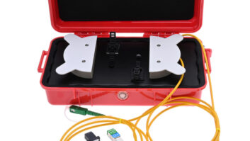
YOU WILL NEED A FEW DIAGNOSTIC tools in your kit. They don’t have to be fancy, but lacking some of the basics can make even a simple problem maddening to trace. A digital multimeter is very helpful for checking wiring continuity and measuring signal levels. A tone generator is most useful — it really beats having an assistant read the newspaper into the microphone to give you something to listen to. Simple ones that generate 440 Hz (international A) or 1000 Hz can be found at music stores.
Hand tools, such as wire strippers, needle-nose pliers, good soldering equipment and diagonal cutters, are also essential. Another useful tool is a monitor speaker, a self-powered, battery-driven speaker with the whole gamut of adapter cables so you can listen to each stage of the audio chain. It doesn’t have to be big or expensive. Computer speakers are very useful for this because you can buy relatively inexpensive units that run on batteries (eliminating any ground loop problems from the test speaker). The ability to unplug an equalizer from the amplifier downstream and listen to audio can often help to quickly eliminate the usual suspects.
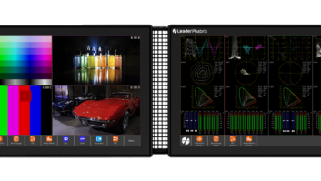
Other tools are impedance bridges, RTAs and O-scopes. Multipurpose test tools from several manufacturers can offer useful functions such as dBu level readings, polarity testing, phase checking, continuity and dB SPL levels. These tools can increase on-site efficiency and range in price from the relatively inexpensive to considerably pricey. You might also check out the various PC-based test systems. Many audio systems now require a computer to set up, so the cost of the laptop is already absorbed.
Finally, a good portable CD player with a test CD is useful to have on hand. These CDs offer a wide range of test tones. Pink noise and intelligibility tracks can help immensely with system setup.
Proper Gain Structure Cures Ills
GET IT AS HOT AS POSSIBLE WITHOUT CLIPPING
Proper gain structure starts with good microphone preamp levels. You want the preamps to be as hot as possible without clipping. A strong singer could induce clipping sooner than a soft-spoken reader. Adjust your preamp gain based on the source, not the little numbers on the panel. Don’t set everything at the noon position because someone taught you that was the best way. Preamp gain will need to be higher for boundary mics in a boardroom than for vocal mics at a concert. It might need to be lower for a hot studio condenser mic than a dynamic mic.
The output of the mixer should be around 0 dBu (or +4 on pro gear) and then maintained at that level throughout the rest of the audio chain until you get to the amplifier.
Proper gain structure will solve a lot of problems. Automatic mixers, DSP boxes, acoustical echo cancellers and equalizers all work better when they have a solid signal to work with. Poor gain and low signal levels will make your amplifier work overtime trying to compensate for the low signals upstream.
BUT DON’T LET THE SIGNAL CLIP
Too much gain at any stage will cause clipping. This sounds like distortion in the audio with multiple overtones even on what should be a pure tone. Putting a test tone into the mixer will make it easy to hear this problem. To solve this, start at the back end of the system. Turn the amp down first (but not all the way). If the clipping goes away, the speakers were overloaded. Higher-rated speakers may be needed. If the clipping is still evident, then raise the amplifier back up and turn down the output of the device feeding the amp. Do this systematically upstream until the clipping stops. Clipping can be induced at any stage of an audio system. The last components you should check are the mixer preamps.