A patchbay is a group of patch panels. When it comes to signal routing, nothing is more basic. Connecting things by plugging circuits together with patch cables goes back to, of course, the telephone company–long before electro-mechanical and electronic switching. Patch panels provide a means of changing and testing signal paths, as well as backup for electronic routing, and are found everywhere in broadcast and production facilities, remote trucks, sports arenas, etc.
While signal connections on wall-mount or rack-mount plates can be considered a form of patching, this article is about monolithic patch panels used as central connection points in AV systems. Patching for video, audio and networks is similar in principle, but equipment differs greatly due to the nature of the signal types.
Video Patching
Patching for video signals (whether analog or digital) comes in the form of coaxial jacks that have a center pin and outer shell. Video patch jacks, and respective patch cord plugs, are designed to maintain the shielding and impedance of the connection. The native impedance for video cabling is 75 ohms, and the original “full-size” WECO (Western Electric Company) patch jack has been around for 50+ years. There is a similar-looking 50-ohm jack, but the two are not physically compatible.
For the most part the WECO jack has been replaced by the smaller mid-size (mini-WECO) jack. These are still 75-ohm impedance, but can handle the higher data rates of HD, 4K and their variants. They also allow greater patch panel density; more connections in a smaller space. As frequencies go up the parts must get smaller, so micro-size jacks, intended for 12Gb video (4Kp60), are starting to appear.
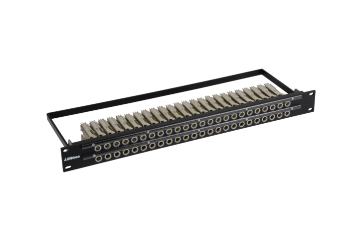
Mechanically, video jacks generally mount individually on a rack-mount panel made of metal, plastic or other material, in two rows of 24 or more. A 2×24 or 2×26 layout is typical for WECO jacks, while mid-size is typically 2×32. Patch jacks and plugs are usually interoperable on the patching side, but different manufacturers have their own designs for how the jacks and panels fit together. Be careful, parts may not be interchangeable!
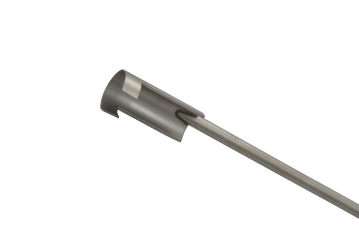
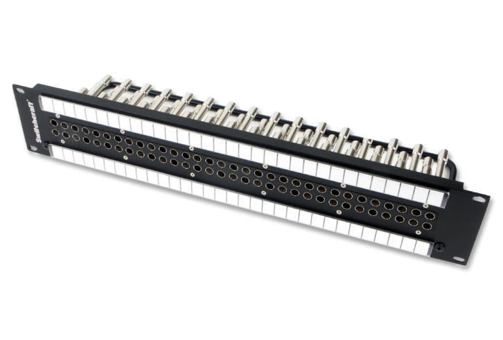
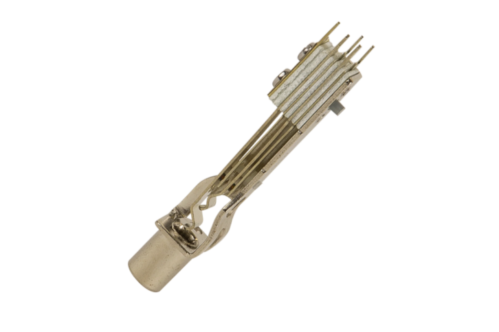
The back side of video patch jacks is the familiar female BNC connector. Because the jacks are close together it is helpful to have a BNC tool handy for connecting and disconnecting cables. With mid-size panels, a special thin BNC tool is required because the jacks use alternating lengths to allow for tight density. Getting fingers in there is nearly impossible, and using the tool takes some practice (see opening photo at top).
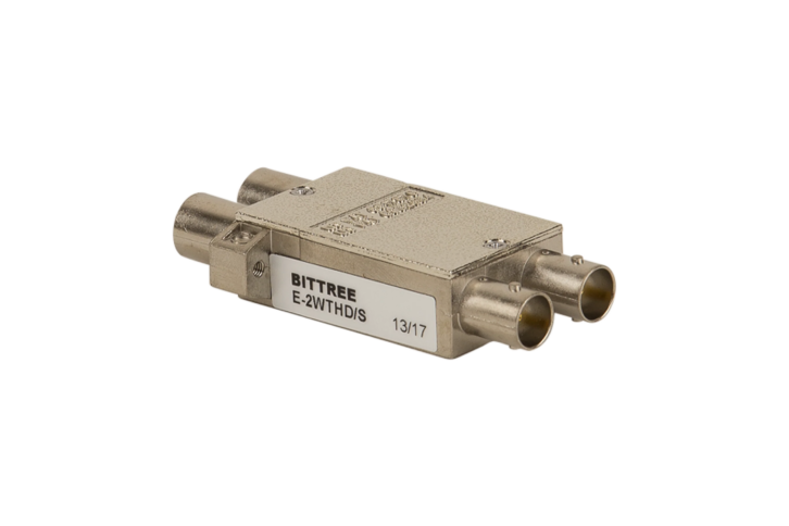
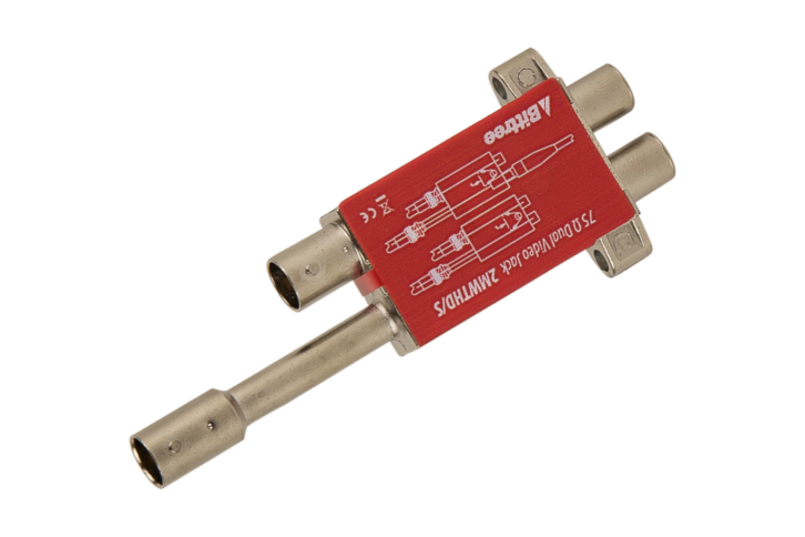
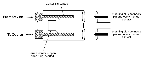
The good thing about video patching is relative simplicity. Because video signals must have a single 75-ohm termination, and cannot be passively split or combined, patch panels are pretty much just rows of jacks. The convention for broadcast patching is device outputs on the top row, inputs on the bottom. The main choice is whether the top row jack is normalled to the bottom row jack. In a “normalled pair” (a single casing with two jacks) the top and bottom jacks are internally connected so that the output signal on top flows to the input on the bottom. That is the normal signal path, unless a patch cord is inserted into either jack.
With mid-size it’s pretty common to use full panels of 2×32 normalling jacks. This is convenient for general use, and happens to coordinate nicely with video matrix routers that often come in I/O sizes based on 8, 16, 32, etc. In the event that the design calls for output and input signals at the same horizontal position, but not normalled top to bottom, single jacks are available. It’s also possible to buy empty panels and individual jacks, which can save a lot of money when just a few patches are needed, say for auxiliary connections that aren’t used regularly.
Audio Patching
Patching for audio follows the same principles as video with regard to outputs on top, inputs on bottom, standardized jacks and plugs, and the concept of normalling. But because audio signals are at much lower frequencies, and are generally not concerned with terminating impedances, the physical components are entirely different, as are the ways they can be deployed. (For more read “Analog Audio Interfacing” at https://www.svconline.com/author/eric-wenocur)
Jacks based on a ¼” standard are often called long-frame, which is another legacy of the telephone company. They are physically sized like ¼” TRS phone plugs, though are mechanically somewhat different. The smaller Bantam (or Tiny Telephone, ie: TT) jack is about half the size, which allows for denser patch panels. Electrically they are the same, with both sizes having terminals for tip, ring and sleeve contacts, plus tip-normal and ring-normal contacts.
Broadcast (telco) style audio jacks are made by stacking together shaped metal pieces and insulators, with solder points on the back and gold-plated contacts where the patch plug inserts in the front. You can mount these jacks to a panel and solder wires to the back, which might be acceptable for a handful. But it’s more common to find full panels of jacks that are pre-wired to some type of quick termination, such as ADC’s QCP insulation displacement punch-down terminal (or similar).
Each QCP terminal is a metal tube with a slit that slices through the insulation when the wire is forced into it (punched down). This type of termination requires no individual stripping or soldering, so is fast and flexible, and typically used with 22 or 24-gauge wire. Strip the jacket off a single-pair audio cable, then punch the red, black and shield wires onto the terminals. The terminal will cut off excess wire when punched. One caveat is that shield wires should not be left bare–use the provided insulating sleeves that help secure the wire. Stacking multiple wires in a terminal is useful for creating mults and normals but should be done with caution to avoid over-punching and severing the bottom wire.
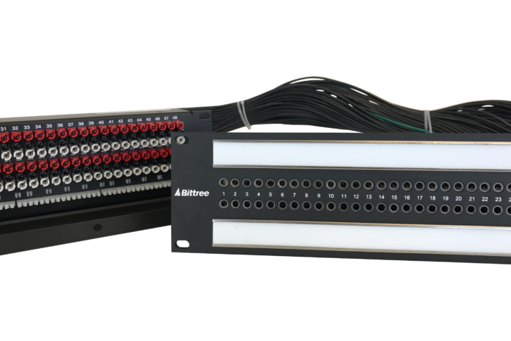
Terminals for 48 (long-frame) or 96 (Bantam) jacks are generally arrayed on a rack-mount backplate (or rear of a box-style patch panel) so that signal wires can be laid in sequentially based on outputs and inputs. Punch-down backplates may have just the TRS terminals brought out, or the normals as well.
Audio patch jacks can be non-normalled, multed, full-normalled, or half-normalled, depending on the application. Non-normalled is self-explanatory. Multing simply means connecting several jacks in parallel, creating a hard-wired passive split. You can create multiples from a specific source patch, or put some “utility” mults on a panel for splitting a signal when needed. Mults are easy to make on punch-down panels by daisy-chaining wires between terminals.
A full-normal is the same as a normal for video. That is, the signal flows from top jack to bottom, and plugging a patch cord into either jack breaks the normal. With a half-normal, if a patch cord is plugged into the top jack, the normal stays intact, so signal flows to the jack below and to wherever the patch cord goes (a passive split). When a cord is patched into the bottom jack, the normal is broken. This is a very common arrangement for broadcast patch panels because it’s often useful to keep a signal going to its original destination (say a mixer input) and also patch it somewhere else (perhaps an IFB feed).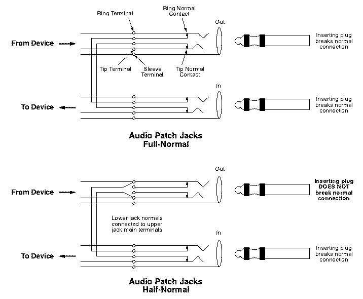
Half-normalling does not degrade the signal at all, but it can create some tricky troubleshooting situations. It’s important to remember that plugging into the top patch jack does not break the connection to the bottom jack; they remain in parallel. So the signal from the top jack can be affected by whatever is at the far end of the cable connected to the bottom jack. For example, let’s say that cable goes to a mixer input, but the TRS plug at the mixer was pulled out and left laying loose. If it touches something metal that grounds the tip or ring contacts, that might cause the signal coming from the top patch jack to appear dead or noisy when, in fact, the trouble is being caused by the normal from the bottom! In this case, plugging a loose patch cord into the bottom jack will open the normal and fix the issue.
Audio patch panels may have a variety of other configurations and terminations, depending on where they are used in a system. Panels can be pre-wired to Elco-Edac, DB25, Molex or other connectors. Some panels are built from jacks soldered to printed circuit boards, rather than freestanding jacks, and may have jumpers or switches to configure normalling. Which to use depends on the application and cost.
There are also audio patch panels intended for home studio or music users that have regular TRS jacks, or even RCA jacks, on front and back. This makes it easy to set up a patch panel by plugging pre-made cables into the back. These are generally not used in professional installations due to cheaper construction, potential unreliability, and lack of flexibility. But they are far less expensive than broadcast panels and can be handy at times.
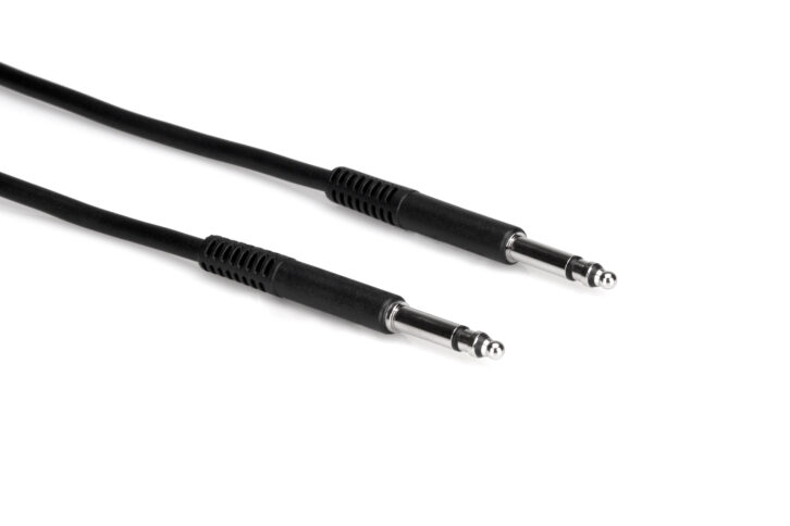
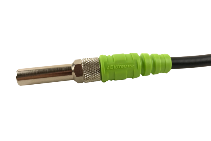
Audio patch cords are made with plugs designed to mate with telco-style jacks (see Fig. 1). It is generally possible to use standard TRS plugs in a pinch, but it’s not a great idea. Conversely, using telco-style patch plugs with standard TRS jacks is usually bad because the contacts don’t mate well. Traditional brass patch plugs will tarnish and cause poor connections. They can be cleaned, but the better option is to use patch cords with nickel-plated plugs.
Lastly, there’s the issue of patching microphone signals. There are times when it just makes sense to have the flexibility of cross-patching mics between rooms, mixers, etc. but it must be done with care. Because mixers and preamps provide phantom power for condenser mics, there is the risk of this DC voltage being patched to the wrong place and causing damage. Inserting and removing patch cords with phantom power on can cause bad pops and even small sparks; better to turn it off when patching. Mic patching is generally done with full-normals to prevent passively splitting the very low-level signals (and potential effects on mic performance from impedance changes).
Patchbay Strategy
When installing video or audio matrix routers, patching can be placed between device outputs and the router, and between the router and device inputs. This is quite common in “mission critical” applications in case the router has a malfunction. It’s not a perfect solution, since you lose the ability to send one source to multiple destinations, but at least critical signals can be patched. Unallocated “utility” distribution amps can also be put on patches and used to make duplicates of signals if needed.
In large broadcast installations patch panels provide insert points in all kinds of signal paths that may need to be occasionally changed or tested. It’s typical to put patch points between production sources (cameras, graphics generators) and video switcher inputs, between switcher outputs and downstream devices, and in monitoring paths. Extra patch points of test signals, camera outputs, and monitor inputs can be quite handy. Again, the aim is to provide flexibility and access for troubleshooting.
General purpose tie lines are another way patch panels are useful. Tie lines are just cables with jacks at one end, say on a studio wall panel, that terminate on a patch panel, waiting for when a connection is needed. Likewise, facilities with multiple rooms often have tie lines between patchbays in order to share resources. Tie lines are neither “inputs” nor “outputs” they are just pathways.
There was a time when I installed dozens of audio patch panels, both analog and digital, as a matter of course, and that has certainly changed. In the video production sphere, embedded and IP-based audio, along with larger mixers, have greatly reduced the need for standalone audio patching. One exception is music recording studios, where the need to patch outboard processors, and rearrange signal paths, is still common. In those cases, some patching is often supplied as part of the mixing console itself, perhaps augmented by an “outboard” patchbay for additional equipment.
Unlike so much in the AV world, patch panels and jacks are passive, mechanical devices, not prone to failures, so rarely the culprit when a signal is lost. Video and audio contact points are gold-plated and don’t oxidize. Noisy audio patches generally need nothing more than a bit of “exercise” with a plug to clean off any dust (manufacturers I have spoken to do not recommend contact burnishers). However, poorly installed connections at the back of the patch panel, such as BNCs not fully seated, will cause trouble.
So why talk about this now, when everything is “going IP”? For one, there are plenty of existing installations that are not IP-based, and may never be, so knowledge of patchbays is useful. Second, IP is not the best choice for every possible application, and patchbays can be important for a facility using baseband signals like SDI.
An IP-based approach, with “everything on the network,” has certain benefits, such as the network being the signal routing fabric. But it also has dangers for mission-critical applications because there is no quick and easy way to re-route signals during a network problem. And network troubleshooting is complicated. Yes, network installations have patch panels, but each jack may not represent a specific source or destination, and it may not be possible to quickly patch things together to get around a failure. At minimum, the design process for building a facility should consider the pros and cons of both IP and conventional signal flow in the particular application.