Sometimes conditions are not good, time is short, or trouble arises unexpectedly. Sometimes you can find a temporary (or permanent) solution that might be pushing the edge of standard practice, or good sense, but still works. Knowing the theory and physics of equipment and signals means knowing when it’s okay to cheat.
Wire & Cable
Working on an audio upgrade at a church, we were replacing two old passive speakers with active ones in the same locations. They were far from the equipment rack housing the system mixer, and the original cable path was unknown. This being a traditional building, the speakers were on the walls of a big open space with a very high roof. There were few viable paths for new cables, and they all involved concrete block, doorways, and whatever else we could not see in the walls.
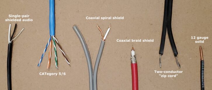
Eventually, I realized that there was already a cable in place—the original two-conductor speaker wire! I knew this would be fine for line-level balanced audio, particularly if the speaker had good-quality balanced inputs. Soldering XLRs onto 14-gauge speaker wire was a little odd, but in the end, it worked just fine, as expected.
Unconventional? Yes. But not wrong. Although most speaker cable has two conductors and no shield, a good balanced input can cancel induced noise on its own. A shield is not needed. For best noise rejection, the two audio conductors should be twisted together, not great in speaker cable, but the line-level audio was already well above most potential noise. I would not try this with a mic-level run, nor make it a regular practice, but in this case, it saved a lot of sweat and cursing!
(For more, see https://www.svconline.com/needtoknow/analog-audio-interfacing)
Similarly, CATegory cable is actually well-suited to analog balanced audio. Even without an overall shield, the four pairs are twisted, and the pair impedance and gauge are appropriate for audio. I recall touring a large FM radio station years ago that had just been upgraded. All the inter-room wiring was on CAT cable and ADC punch blocks—no shielded audio cable at all.
If there’s just no time to get more audio cable, run a piece of CAT5 or CAT6. But it’s important to note that using CAT cable for audio assumes the signal is properly balanced, either by the equipment at each end or with a pair of “balun” converters (which use transformers). Sending unbalanced audio will almost certainly result in noise, and possibly inductively coupled audio between pairs.
(For more on transformers, see https://www.svconline.com/industry/transformers-the-hidden-gem)
CAT cable is fairly ubiquitous in buildings, and handy for many purposes, so might provide a ready-to-use signal path (assuming you can find the IT room at the other end). Most kinds of serial data, including DMX, work fine on CAT cable, and it’s great for camera tallies, GPI/O contact closures, low-voltage DC for lights or relays… any time a few extra conductors are needed. Of course, there’s HDBaseT, and products designed to put other complex signals on CAT (with realistic constraints for length and other parameters).
Single-pair or multi-pair audio cable is also suitable for many of the same purposes. I have powered remote equipment and lit many a DC “on-air” light with some single-pair audio, like Belden 9451. Obviously, speaker wire can do the same but is more cumbersome to work with. So can plain old two-conductor “zip cord” used for home appliances and lamps.
Speaking of zip cord, what’s the difference between 14ga. “speaker” wire and 14ga electrical wire, like an AC extension cord? Nothing, apart from the way they are constructed and sold. Electrically, they are interchangeable for audio speaker purposes. What about running AC power on speaker cable? Electrically, it’s fine, given the appropriate gauge for the current required. But in an environment where speaker wire is assumed to be carrying audio, this raises some serious safety concerns. I expect it also violates numerous safety codes.
Interestingly, video or RF coax is not quite as useful for other applications. It is functionally two conductors, and fine for low voltage DC, contact closures, and the like, but poor for audio because it’s not a twisted pair. For unbalanced audio or unidirectional data…okay for short distances.
Can you use 50-ohm coax in place of 75-ohm, or vice-versa? Sure, it will work up to a point, but cable impedance matters at the frequencies of video and RF signals, so performance is likely to suffer. Plus, the connections where 50 meets 75 will cause impedance “bumps” (discontinuities) that can create detrimental signal reflections. Unless you have the right test gear, there’s no way to tell how much the signal may be compromised, and therefore how much trouble you might have. For short distances, or a last-minute jumper, probably fine, but not advisable for proper installs.
I have even found that it is sometimes workable to sub a piece of multi-mode fiber for single-mode, or vice-versa, at short lengths. This depends greatly on the transceivers, wavelengths, and type of connectors, but nothing will be damaged by trying. If it works to get past a rough patch, great. Replace with the correct type later!
Lastly, lots of cable is “rated” for various signal types, such as CAT6A for 10Gb Ethernet, or “12G” coax for 4K SDI video. The ratings suggest the cable’s capability at higher bandwidths, but do not limit use of the cable at lower bandwidths! For example, it’s fine to use 12G coax for any SDI video (though it may be poor for analog video).
Video Workarounds
It’s well understood that video connections on coax are supposed to terminate with 75-ohms at the final destination. This is because video cable (both analog and SDI) behaves like a transmission line, where the combination of source and termination impedance results in the correct voltage level. This is critical with analog video because the signal on the wire is the actual video, not a digital proxy. So an unterminated connection produces twice the voltage, causing distortion at the receiver, while double-termination results in half the expected signal level.
The same is true for SDI, with regard to the voltage on the wire, but that voltage represents digital data, which is then decoded into a video signal. What really matters is whether the receiving device can recover those data bits accurately. Proper signal level at the receiver is important, but receiver circuits will often tolerate some variation.
In my experience, neither unterminated nor double-terminated SDI is uniquely problematic most of the time. Without an eye-pattern scope, it’s not possible to know how compromised the signal may be, but if it works, it works. Or, more accurately, it works with that particular combination of cable, connector, and input circuit, all of which affect recovery of the digital bitstream.
The upshot is that you can sometimes get away with “splitting” an SDI signal to two destinations. This will cause an impedance discontinuity and possible double termination, but if both receiving devices recover the signal, it’s workable. Again, this is not the way to build finished systems, just a temporary fix.
On a different topic, when working with genlocked equipment, note that any analog composite video can usually be used in place of blackburst as a sync signal. For example, a camera with composite out could be the “sync generator” for a genlocked system if necessary. As confirmation, when the reference is connected or disconnected from a device, there is usually a momentary glitch in the picture as the device relocks.
One other note about genlock, which is that if a distribution amplifier goes down, resorting to passive loop-thrus should be fine. There is nothing inherently bad about looping as long as each loop is non-terminating. Even a double termination may be tolerable for genlock because the absolute analog video level doesn’t matter, as long as the receiving circuits can detect the sync pulses.
(For more on genlock, see https://www. svconline.com/industry/sync-genlock-and-timing)
Power Supplies
The bane of everyone’s existence is cheap power supplies–the most likely thing to die at the wrong time! Since switch-mode supplies have largely replaced linear designs and are a commodity product, quality is unpredictable. Fortunately, singlevoltage power supplies are often interchangeable.
The supply must match the voltage required by the device, typically something like 5 or 12VDC, and be able to provide at least as much current (amps) as the device requires. If the supply is rated for higher current, that’s okay; it will only provide what is needed. If you can’t find the required current on the device or in a manual, it can be calculated from the stated wattage (current = watts/volts) or use the old supply as a guide. For reference, small throw-down converters typically use less than 10W.
Of course, the plug must match or be very close in both center pin and outer dimensions, and the plug polarity must match–typically center pin positive. If necessary, it’s perfectly fine to cut the plug off of the dead supply cable (keep plenty of length) and splice it to a new supply, but knowing which wires are positive and negative requires a meter. Test the voltage coming from the new supply to determine wire polarity. And use the ohmmeter function to check which wire carries the center pin on the old cable. If no meter is available, try connecting the wires with a best guess and see if the device works. If not, reverse the splice and try again. This is not recommended practice because some devices could be damaged, but many will tolerate a brief reverse-polarity condition.
Also note that power supplies for AC voltage may look exactly like those for DC, so read the label carefully. In some cases, the device being powered may actually require AC instead of DC, and some rare devices will take either. But those cases are unusual with AV and broadcast equipment.
For devices that run only on batteries (with no batteries to be found), a suitable voltage power supply can be connected to the battery terminals with clip leads. For that matter, clip leads can connect a power supply to a device’s power input jack if the plug is the wrong size. Worst case, open the device up and clip directly to the jack terminals on the circuit board.
Just after this article published I was connecting a conferencing video bar and discovered that the power supply was missing. After searching the office for another 12V power supply (with the right size plug and sufficient current capacity) I was about to give up, but then decided to take a last look in my car. For years I’ve carried a Micro-Start XP-1 battery pack to jump start cars. It’s an amazing device and turns out that this model also has output jacks for 5V (USB) 12V and 19V, plus a DC cable and assortment of coaxial power adapters! It ran the video bar for 30 minutes while we tested, and barely lost any charge. Unfortunately the XP-1 Gen 2 does not have the 12 and 19V outputs, but the old ones can still be found online.
(For more on power supplies, see https://www. svconline.com/industry/practical-power)
Going MacGyver
Years ago, I was on a trip in Panama and attended a presentation at a venue with low-tech AV. The old wireless mic cut out constantly. During a break, I took a look and discovered that the receiver had no antenna. Aha. I can’t recall now if I stuck a paper clip or piece of coat hanger into the antenna jack, but it helped. A poor antenna is better than none!
(For more see https://www.svconline.com/industry/mysteries-of-rf)
If a BNC plug breaks, you can strip the coax and use the bare wires; tape the mess in place so the shield braid touches the BNC jack outer ring. You can also plug bare wires into an XLR jack (they might need to be folded over at the end to make good contact). Same is true for pushing wires into a female D-sub connector.
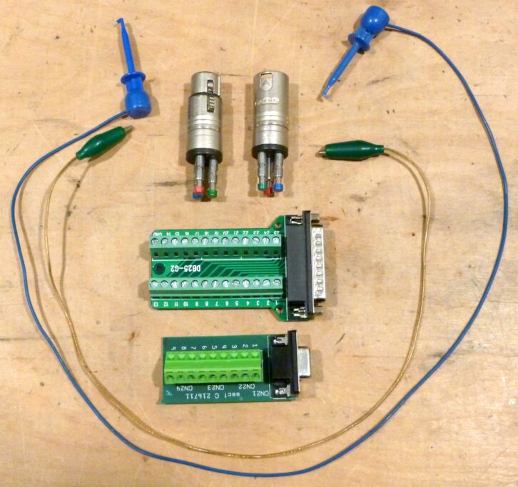
Alligator clip leads can be used to reconnect the ends of broken cables or connect a wire to a terminal or contact point. I have many test leads and jumpers with EZ-Hook clips, which are more compact (though difficult to use with XLR pins). I also have some handy XLR adapters with spring terminals and some D-sub breakouts (Fig. 2).
Many people may not know that Ethernet up to 100Mb/s only uses pins 1-2 and 3-6 of the RJ45 (orange and green pairs in T568B wiring). If you’ve got the plugs but no CAT cable, two pieces of 24ga single-pair audio could be used to make a patch cable. Or the unused pairs in a CAT cable could carry another signal running alongside (this is actually done in digital snakes based on AES50). However, if the tech requires 1Gb or higher, then all four pairs are needed.
In a worst-case power supply scenario, say there’s a critical box that only runs on POE, but no source of POE is available, it’s theoretically possible to open the box and connect DC power to the circuits after the POE conversion. Admittedly, this would require some skill, knowledge of circuit design, possibly schematics, and nerve. But if the gig is going to tank anyway without that box, maybe worth trying.
Then Again…
Readers may notice that the workarounds mentioned above tend to revolve around mostly passive and analog technologies. Unfortunately, the more complex the technology, the fewer workarounds are possible. What can you substitute for a broken HDMI cable? Another HDMI cable. Open one up to see why!
Which interfaces on the back of a computer or other piece of equipment might allow for an emergency workaround? HDMI… USB… DisplayPort… Thunderbolt? Thunderbolt is particularly problematic because it uses USB-C (or mini-DisplayPort) connectors, but the cables must include special circuitry. If it doesn’t have the Thunderbolt icon, it probably won’t work.
If the digital snake for a mixer goes down, you are SOL without a spare (or an analog snake). If the Dante network goes down, same thing. Really, if the network switch in the center of any “over IP” transport technology goes down, another switch is required. And it probably can’t be any cheap switch sitting in a closet, unless the utilization is very basic.
In this realm, finding workarounds is more about rethinking a particular signal flow or replacing an entire technology with another. If you can’t use HDMI, can you use DisplayPort as a sub? What about VGA? If the native Ethernet port doesn’t work, how about Ethernet via an adapter or dock?
Maybe you can get files from device A to device B by mounting both as shares on another computer. I once needed to update firmware on a device and had no internet. I managed to download the firmware to my phone via cellular and transfer the file to the device via USB. Really didn’t think that would work!
If it helps, you can usually connect two Ethernet devices directly together, forming a tiny network. In the past, this might have required a “crossover” Ethernet cable, but modern gear will auto-detect the connections. Then you must manually enter IP addresses since there will be no DHCP server. This might be useful to connect a computer and another device for configuration or connect the computer to a Wi-Fi access point.
Then again, sometimes low-tech comes to the rescue. If a USB audio interface craps out, there might still be native analog audio on the computer. Analog audio is truly one of the most universally adaptable signal types; plenty of equipment that only handles digital video still includes analog audio. Challenging situations call for thinking “outside the box” and knowing what is possible.