You can make all the signals digital, but sound is still an analog phenomenon. And sometimes using analog audio equipment, or analog connections, is still the best choice because analog audio requires little technical overhead—it’s ubiquitous, it works. But analog audio interfaces have their own history, methods and rules. Many analog audio conventions evolved from techniques used by ye olde telephone company (back when there was one phone company and simple analog phones), and over time were standardized by the Audio Engineering Society and other organizations. If you’re using analog audio, and especially if explaining it to a digitally-minded client, team member, new hire, or volunteer, there are some basics you should be able to articulate.
A Bit About Decibels & Test Tone
Decibels are used everywhere in professional audio so it’s worth a brief introduction. The decibel (which is, in fact, 1/10 of a Bel) is a measurement unit with two important characteristics. First, the dB is not an “absolute” measure of quantity (like a gallon). The dB is used to represent a ratio of two quantities; in audio that usually means the difference between a measured signal level and a reference level.
Second, the dB scale is logarithmic, so dB values do not change linearly with signal values. For example, if 1 volt is the reference, going to 1.12V is a 1dB increase. Going to 10V is 20dB, going to 100V is 40dB. The logarithmic scale effectively compresses the numeric range needed to express large differences. It can be useful to remember certain telltale ratios, such as 6dB being a doubling or halving of voltage.
Measuring these values is really not possible with an audio signal that changes, so steady-state test tones are used. A very common test tone is a 1KHz sine wave. This can be generated by both test equipment and functional devices (either hardware or software). Tone is a known good signal, with predictable behavior, and provides a reference point for audio levels. Using tone to check levels in an audio system can be indispensable for setting gains and troubleshooting, especially if you are not familiar with the system at hand.
What You Need to Know About Levels
Analog audio signals in professional systems fall roughly into three level categories: microphone, line, and speaker. Line level typically runs between equipment in a system and originated with phone company transmission lines which were terminated in a 600-ohm load impedance (something that’s no longer a concern). Since transmission lines are concerned with power transfer, a reference level called 0dBm was defined as 1 milliwatt of power into 600 ohms. This equates to .775 volts AC, when measured with an RMS voltmeter.
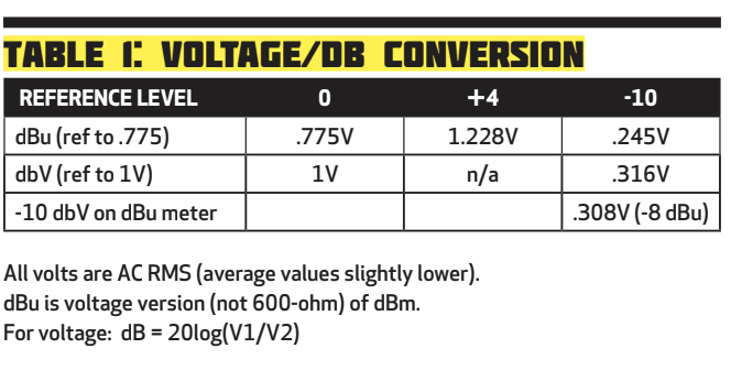 You may still see 600-ohm termination on older equipment, but gear we use today generally has high-impedance inputs. The reference level for high-impedance systems is called 0dBu and is also equal to .775V. When we talk about professional line level as “+4” this actually means 4dB above the 0dBu reference, which is 1.228V, from the formula dB = 20log (V1/V2). Using tone, this voltage at an input or output would give you “0” on a VU or analog level meter in the equipment. The term dBu is often included in specs to clarify the reference level, but for most purposes it’s understood that +4 means professional line level in common use, ie non-terminating.
The other common line level, mainly for consumer gear, is often referred to as “-10.” This is actually referenced to the dBV standard, where 0dbV is 1 volt. So -10 generally measures at 316mV. You will also find some gear that operates somewhere in between -10 and +4, including musical instruments and Mackie mixers (which equate “0” on their meters to 0 dBu at the output jack, not +4). (Table 1)
The terms -10 and +4 provide an idea of the signal level range likely to be present, but don’t say anything about the actual signals. Most decent pro equipment will handle at least +22 dBu (9.75 volts) at an input before overload. In that case there’s about 18dB of headroom at the device input between reference tone at +4 dBu and clipping. Similar specs can be found for -10 equipment. (Note that digital systems, which define a level of “0” as full-scale (all bits used) usually make -18 or -20dBFS equivalent to 0VU in the analog world. This is where reference tone should sit.)
Incompatible levels is one of the easiest ways to create distortion or noise. Mic level signals (roughly -60 to -30 dBu) require a preamp, in a mixer or other device, to raise them to line level. While speaker level, power high enough to create substantial volume from a loudspeaker, should generally not be connected to anything else. Similarly, plugging line level into a microphone input can easily cause overload distortion, though it should not damage anything (unless phantom power is turned on). Lastly, connecting -10 and +4 equipment together generally requires some type of active or passive “level matching” device. These are often used when including consumer gear in pro installations.
What You Need to Know About Impedance
In the 600-ohm-terminating days, the output impedance of the source had to match the input impedance of the receiving device. If the input impedance was higher than 600-ohms, the signal level would increase. If it was lower the signal would decrease. (This is still the case with video, where each connection must have one, and only one, 75-ohm termination to get the correct level.) Today the general rule is that the input impedance of a device should be at least 10 times the output impedance of the preceding device, and most equipment is designed this way. Consequently, you can connect outputs to inputs without worrying about unexpected level changes. You can even connect one output to several inputs (splitting or bridging the circuit) without affecting level because several high input impedances in parallel will not “load down” the preceding output.
This 10:1 rule does not work in a few situations. One is with power amplifiers and speakers, where the impedances need to be correctly matched for optimum power transfer (please follow the manufacturer’s directions). Another example is fancy studio mic preamps, which may have switches to select different input impedances because this can sometimes alter the sound of a microphone in a desirable way.
Unfortunately, impedance is often discussed incorrectly. A level matcher for converting between -10 and +4 is sometimes called an “impedance matching” device, which in most cases is either incorrect or unimportant. In practice, impedance is a minor issue in modern systems with well-designed equipment; it is rarely the actual cause of audio problems.
On Being Balanced Or Unbalanced
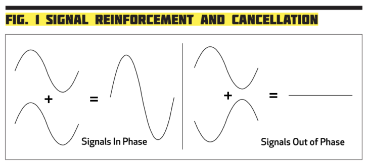
The phone company also developed the concept of balanced lines. In this scheme, the principle of signal cancellation is used to reduce electromagnetic interference noise (RFI) in wiring. Referring to Figure 1, when the two sine waves are added in-phase the peaks and troughs combine, doubling the level. When they are 180-degrees out of phase the peaks and troughs cancel, so no signal.
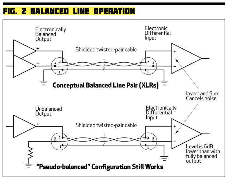
A balanced connection sends identical audio signals, but 180-degrees out of phase with each other, on a pair of twisted wires to the next device. That device has a differential input (either electronic or transformer) which means that it will invert one of the two signals and then sum them together. By inverting and summing, the differential input produces only the difference between the signals on the pair of wires. Our audio content is maintained because the two signals sent out of phase will combine positively. But any noise that impinged on the wires along the way is in-phase on both (known as common-mode), and when one side gets inverted they cancel out. Properly done, balanced audio on twisted-pairs rejects noise so well that the cable does not even require a shield.
What is often misunderstood is that it’s the differential input that cancels the noise, and it will do that regardless of what audio signals are on the wires. Even if one wire has a signal and the other has ground, the differential sum will still cancel the common-mode noise and preserve the audio. This is the configuration of some outputs on mixers, where a block diagram might show a TRS phone jack with the Ring terminal connected to ground (hopefully through a resistor). These still provide the advantages of balanced lines as long as the next device has a differential input (and it sees two closely matched source impedances). See Figure 2 and the link below to Jensen Transformers application notes.
Unbalanced connections, such as the RCA (phono) connector, have one signal wire and a ground, which is configured as a shield around the signal. These are mostly okay for short distances, but they can cause noise problems. Not only do unbalanced lines not reject electromagnetic interference well, but noise can enter equipment on the shield because it is actually part of the audio circuit. Generally, the same level matcher that converts between -10 and +4 levels also converts between unbalanced and balanced lines—another reason to use them!
Connectors Make It All Happen
There are many connector types in use and sometimes the same connector is used for very different purposes. A common example is the 3-pin XLR (sometimes called Canon) connector, which is used for both microphones and balanced line-level signals. They may even be used for DC power or DMX lighting control. Just because the connectors match does not mean they should be plugged together! (Table 2)
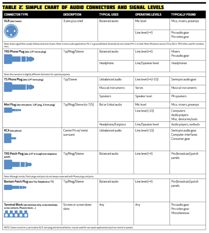 Another phone company legacy–and easily misused–is the quarter-inch phone plug. The three conductor tip-ring-sleeve (TRS) version is found everywhere on pro equipment for balanced line-level connections. The two-conductor (TS) version is only good for unbalanced signals, and traditionally used for electronic musical instruments. Whether it is wise to plug one type into the other depends on whether you’re dealing with a balanced input or balanced output circuit, and which side has the ring terminal (or not).
As a rule, avoid situations that short one side of a balanced output to ground, as this may cause distortion. This might happen if a TS plug is used in a TRS output jack (the R contact of the jack will touch the shield because there is no ring on the plug). Conversely, leaving one side of a balanced input unconnected, as might happen if a TRS plug is used in a TS output jack, can result in no signal, or a low signal, or a noisy low signal.
The TRS phone plug is also used for headphones. In this case the connector is carrying two unbalanced signals, left and right, with a common ground. The same is true for audio outputs from computers and music players, using the ubiquitous stereo mini phone plug. Feeding those into a pro audio system requires, at minimum, an adapter which breaks out the left and right channels. If they must feed a balanced/+4 device, you may want that level matcher. Cell phones can have a variety of mini-plug configurations using TRS or TRRS jacks; don’t assume that a given plug type will do what you expect.
Note that the two signals used in a balanced connection are often referred to as + and – (with + being the in-phase signal), or high/low or hot/cold. For an XLR the + is usually on pin 2, the – on pin 3, though there are exceptions. Ground/shield is always pin 1. For TRS, the + is tip, the – is ring. For headphones, left channel is usually tip, right is ring, shield is common to both.
The bottom line is that some configurations may function if the wrong connector or wrong signal types are inter-mixed, but the audio result may not be optimal. Or it may not work at all.
Important Points to Note
- Use specs and diagrams to determine what signal and connector types are present on equipment. The connector does not define the signal!
- Pay attention to compatible levels between equipment and to level changes in a signal path. Lots of conversions back and forth between +4 and -10 (or mic and line level) can add noise.
- Use balanced connections whenever possible, keep unbalanced connections short. For long runs (say over 10 ft.) consider adding active converters or transformers—especially when going between different rooms or equipment on different power circuits.
- Connecting balanced/+4 equipment to unbalanced/-10 usually requires a level matcher (which also handles the balancing conversion). There are ways around this, but you must understand how the circuits work!
- Transformers are less common for input or output balancing, but they behave differently than electronically balanced circuits and require special considerations.
- Generally, you can split a line-level output signal to two or more inputs, but do not passively combine outputs together. This is the wrong way to “mix” signals because it can cause distortion in the output circuits. Depending on the circuit design it may work but is not advisable.
- Learn how “legacy” equipment actually operates. For example, an analog turntable for playing vinyl records may have RCA plug outputs, yet the signal from the cartridge is way down at mic level. But it cannot feed a mic input because records require special equalization to sound correct. This situation requires a real phono preamp.
- Phantom power is a DC voltage which rides along with the audio signal to power condenser microphones. Plugging anything other than a mic into a jack with phantom power can cause damage. Keep it turned OFF unless it’s needed!
- Professional intercom systems also send DC voltage with audio on XLR connectors. This is known as a “wet” intercom line and must be treated carefully.
A Few Useful Links
https://www.jensen-transformers.com/application-notes/
https://www.dk-technologies.com/pages/publications/papers/Audio/Audio%20Levels.pdf
http://www.shure.com/americas/support/downloads/publications