In the July 2025 issue of SVC, I gave some examples of projects that were hampered by the architecture and construction process (https://www.svconline.com/ industry/can-this-be-fixed). One of those examples was a relocation of a distinguished university’s video production studio, which I had initially built in 2013. The school was moving out of its original location into a nearby building that was undergoing extensive renovation. Planning had started in 2023, and early in the architectural process they had done a layout of a studio suite, including control room, equipment room, green room, etc.
By mid-2024, when I was officially brought on as the “studio engineer,” a construction permit set had already been issued. But I noted various problems with the working architectural design and made numerous suggestions for improvements, many of which I considered essential to having a solid production facility. I am happy to report that by spring of 2025, most of my changes had been incorporated, and we were proceeding with a schedule for dismantling the old studio, relocating, and reinstalling the new one during the summer of last year. I had also begun the technical system design for equipment, wiring, and other infrastructure.
This article is a diary of the move, which included a few unusual elements. While this is a production facility, so not strictly “AV” in some respects, the issues and solutions are often the same, as are ways to leverage vendor support and engineering skill in a project, especially as broadcast and AV continue to converge.
Physical Space and Infrastructure

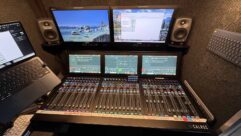
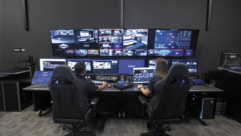
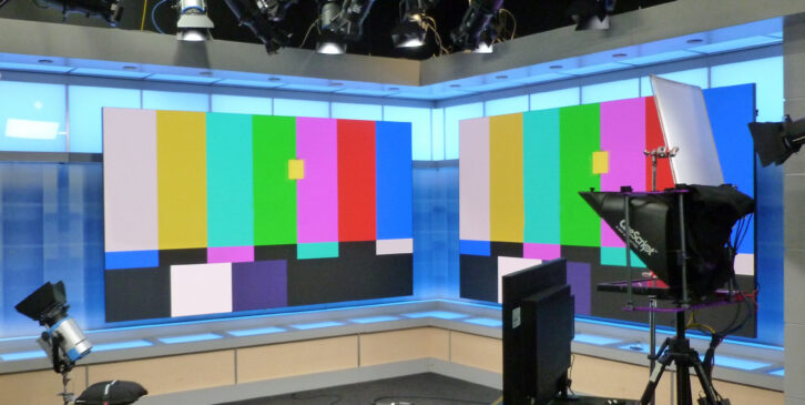
Heading into the summer of 2025 the school would be essentially closed, so we were free to decommission the old studio. Once the new studio suite was clear of major construction we did the technical disassembly at the old location (removing equipment, lights, and some wiring) and coordinated with the school’s movers to take that to the new building in the first two weeks of July. Since the two locations were only blocks apart, we were able to use plastic moving crates and dollies, rather than cardboard shipping boxes, a distinct plus. (Fig. 1, 1b, 1c, 1d)

The studio was moving from an overall space of about 900 square feet for all rooms to a generous 2200 square feet, which allowed a great deal of freedom in how the spaces could be used. The floor plan we had worked out meant that the existing set would fit well, as would the large control room desk, and there would be the luxury of ample storage space. It was also roomy enough to accommodate all the moving crates, old furniture, and studio lights, and still have enough space to bring in and reassemble the set. (Fig. 1e)

On the other hand, due to how the building was constructed at ground level, the basement studio would have a hard ceiling at about 14ft over half the space, and only 11ft over the other half. This put the lighting pipe grids at 12’ and 9’ respectively— rather low on one side. More importantly, the high side, where the existing set would go, was on the opposite end from where I had expected based on early designs. Unfortunately, this was not confirmed until after I had specified the location of conduits, connector panel boxes, and power receptacles. I was able to compensate somewhat by swapping the contents of the two connector panels so that the primary connections would be in the right places.

Moving the set to the other side of the studio also put it in the wrong direction from the planned control room window, which necessitated turning the control room desk and multiview display 90 degrees. This meant that standing room behind the operators would be more limited, but it’s still quite spacious.
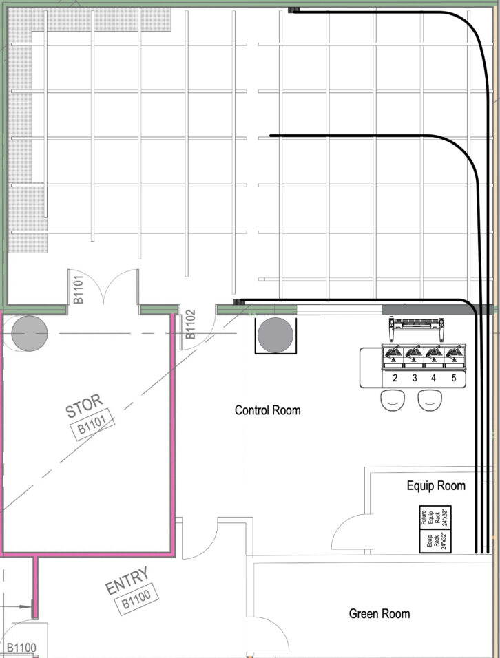
One tricky aspect for studios is coordinating the lighting pipe grid and power receptacles nearby to feed the lights (in this case, all LED instruments with 120V Edison plugs). Early on, I provided diagrams for the preferred grid layout and location of receptacles–powered among several 20A local circuits. As is often the case, some confusion ensued in the process, and for a while, we were not sure what would actually go up. Ultimately, it worked out fine, despite minor errors. I attribute these mainly to having too many links in the chain of contractors and subs, causing information to be lost or misunderstood in the process. Much credit goes to the school’s owner advisor (aka owner rep) for making sure that real problems were addressed!
Studio Set and Screens

When I was officially brought onto the project, I pondered how to move the existing studio set between locations (the school was not interested in starting over). Having been around for the first build, I had an idea of what was involved and was quite sure that I did not want to do it myself. I reached out to Gotham Scenic, the original set builder, to see if they would handle it as a complete package—disassemble, truck over, reassemble— to which they agreed. They sent someone for an initial survey, and I was able to supply a few photos from the original install (apparently, there were no shop drawings to be found).
After some back and forth on process, parts, and pricing, we scheduled the move for the end of July 2025. Gotham would send a truck with three techs, tools, and spare parts, and hire additional crew locally. Since the old studio had already been cleared of equipment, the space was manageable. With full use of a single elevator at the old building, though not a freight elevator, disassembly and load-out took most of a day. The following day, at the new building, only one of multiple elevators was running, so we had to share with construction crew, which slowed the load-in substantially.
Nevertheless, reassembly of the set took only another day and a half, including repair of loose laminate and working out some tricky overhead supports in the new space. I cannot say enough about the professionalism and skill of the Gotham Scenic crew, both staff and local. If you work in live production or theater, you’ll understand the can-do attitude, care for property, and attention to safety that they brought. The smooth set move was a credit to good planning and great people. (Fig. 2, 2b)
One other part of the set move that Gotham handled was removing sections of the 1” tubular steel frames that supported six 85” LCD monitors in the original design. Those displays were a central part of the set in 2013 when LG donated them for the studio. The set was actually designed around them, but sentiment leaned toward moving to a different, more contemporary, approach, which required different mounting.
Early in 2025, the school had begun talks with LG about replacing the old displays and looked at various options. The choices came down to a grid of 55” thin-bezel LCDs, or two 130” All-In-One direct-view LEDs. I spent some time with the studio manager thinking out how those screens would fit and how he would set up camera shots. We also took a studio camera to the LG offices to see the products and consider possible moiré problems (more on that later).

We decided that the 130” dvLEDs were the best choice, and I suggested it might be possible for them to slide laterally within the set. The displays had to be mounted to the existing frames, and I felt confident that making them move would be only moderately harder than having them fixed. This would be a custom solution, and there would be little room for fudging later since I had to know what I was doing by the time Gotham came with their band saw.
These particular displays are built using a mounting frame (normally attached to the wall) and two rear case sections that attach to the frame and join together. That creates a single unified structure, with all the driver circuitry and wiring, into which 64 small LED panels are magnetically mounted from the front.
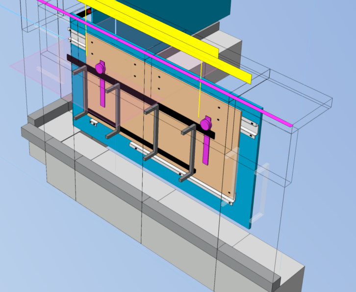
Using LG documentation, and measurements of the set, I built a scale 3D model in CAD to work out how the screens would mount. The design uses hardware made for very large barn doors, with 5” rollers that ride on 3/8” steel track. The CAD model allowed me to “mock up” the entire affair, including how the track would mount to the set, how the rollers would attach to the displays, and how much the displays could move laterally. (Fig. 3)

The end result uses sheets of 3/4” birch plywood as the substrate to attach the screen mounts on the front and the rollers on the back. The barn door hardware was designed for a door to be under-hung, with the door’s center of gravity directly beneath the track so it would hang roughly vertical. But since the whole screen assembly had to hang in front of the track, it was necessary to add some guide rails further down to keep the screens vertical. Those were done with wood 1x2s mounted on screws for adjustability. (Fig. 4, 5)

Putting this together was a bear. Knowing we would be drilling a lot of holes in heavy steel stock, I consulted a machinists’ group on Reddit and purchased some industrial cobalt drill bits and cutting lubricants. Fortunately, there was plenty of room in the studio to lay the plywood flat (on the wheeled moving crates) and do all the marking, drilling, and assembly of the screen mounts. The screens are approximately 10ft wide, but mount on 4x8ft plywood, the largest standard size (helpfully brought along by Gotham in their truck).
LG ships the screens in large road cases with all the parts and hardware to assemble on site. With a slow and careful process, we got the first plywood/ mount combo together and hung it on the track. That in itself was quite heavy and challenging to put in place. Then the two halves of the case drop into keyhole slots and are joined together with locking hardware. Finally, the LED panels were unpacked and fit into place.

The total weight of one screen assembly is around 450lbs, and once up, they were not coming down again. So, electrical connections and adjustments to the guides for verticality had to be done by squeezing between the screens and the lower half of the set. Not fun, but doable. The screens can shift roughly two feet side-to-side and move pretty easily after the addition of some “magic” furniture glides on the 1×2 guide rails and pull handles on the outer edges. (Fig. 6, 6b, 6c, 6d)

Despite the CAD modeling, getting all the pieces to fit as intended still took some fudging in places. The most serious problem was that the right screen tended to “droop” slightly when rolled into the corner, either due to flexing in the support structure or shifting of the set frames once all the weight was added. It was only noticeable when the two screens met, but I was able to fix it by having a machine shop make a tiny steel ramp that sits on the track. When the wheel rolls up the ramp, it lifts the side just enough. After a great deal of careful tweaking, it’s possible for them to meet in the corner almost seamlessly. At least it looks seamless on camera!

Another major upgrade was studio lighting, replacing a combination of tungsten, LED, and fluorescent. The old studio was all 3200K color temperature, and we wanted to move to 5600K, which tends to work better with video displays, as well as replacing any remaining tungsten fixtures for power and heat improvement. LED soft panels provide basic key lighting, with Fresnels for fill, backlights, highlights, etc. A handful of ellipsoidal (“Leko”) fixtures are used to light the set around the video screens.

It was possible to replace the 375W halogen lamps in the ETC Source4 ellipsoidals with LED light engines, which was less expensive (and less wasteful) than buying new lights. The new Fresnels are Arri L5-C Plus models, which are fully color-adjustable. We used a few of the old KinoFlo fluorescents for lighting the green screen, putting in some 5600K tubes to match. There was no good reason to replace the ETC Element lighting board, although it is quite complicated to use. All lights are DMX controlled, with an 8-way splitter on the grid to provide convenient grouping and cable runs.
The set also contains extensive in-set lights, with RGB strip LEDs behind diffusion panels and white downlights in the top canopy. To my surprise, the strip LEDs, power supplies, and DMX decoders survived the move and rebuild, so needed nothing but new addressing. The MR16 halogen downlights were replaced with whiter LEDs and are controlled via a DMX dimmer pack on the grid above.
One pleasant difference between a working studio and typical AV installs is that it’s not necessary to hide or disguise the technology. A neat and attractive space is important, but it’s understood that studios have cables, light stands, cameras, ladders, etc., out in the open. This relieves some of the extra effort often spent to conceal the tech.
Electronic Systems
The new studio and control room would be functionally similar to the original, but this was the time to update certain equipment. That meant balancing potential new capabilities, and ten years’ worth of technology improvements, against the available budget (and my general dislike of replacing perfectly good equipment that’s working). Initially, my mandate was to keep costs down, as management felt that the studio was a useful but not critical feature for the school. However, as other factors in the campus plan changed, this studio became more important, and we had more leeway for upgrades.
Some equipment was removed due to not being needed anymore or never fully utilized in the first place. This included a Compix character generator, an original AJA FS-1 converter, and a DVD recorder. Other items were ready for replacement due to age and changes in technology. The old VGA/USB KVM switch was upgraded to an Adder IP KVM product. The Vaddio AV Bridge UCC interface, which was quite innovative in 2013, had been overtaken by simpler products.
Another piece that became surplus was a TV One Coriomaster wall processor that had been used to create a unified canvas across the six portrait displays. This unit was loaded with cards for HDMI, SDI, and HDBaseT and is still a current product. But the new dvLED displays take a single 1080p HDMI input, like a very large TV, which works well because they can be fed from the SDI router using simple converters. Any router source can be put on the screens, including two upgraded Brightsign media players.
Obvious keepers included the Soundcraft Expression audio mixer, Sony PVM OLED reference monitor (a great piece that is no longer available), and other video monitors in the control room. The RTS intercom equipment was fine, as were audio speakers, a Tektronix rasterizing waveform monitor, and an Open Gear frame with various cards and open slots. I saw no need to replace the single equipment rack, video patch panels, studio connector panels, or the TBC Consoles control room desk (though it required some modification as the layout would be flipped).
 Critically, the studio’s video server, utilized to record a switched Program and three camera Isos, was still working but well past end of life. In 2013, this server had been unusual for having four SDI channels configurable in any combination of record or playback. By 2025, there were a few other potential products, but this Linux-based server had been so bulletproof that I decided to stick with AQ Broadcast, the manufacturer in the UK. This also reduced the learning curve for studio operations as the UI is virtually unchanged. I surely wish more manufacturers would follow that approach!
I also chose to replace the 32×32 SDI router, mainly because I greatly disliked the hardware control panels and difficult configuration process of the old one. Plus, I wanted a router that could handle 4K, although there is no immediate need. The reality of this studio is that it may never need more than HD because of the content they produce, but I felt that the router and system cabling, at least, should be 4K capable.
In fact, I opted to keep the Panasonic AW-HE120 HD PTZ cameras because they work great and do what is needed. The one problem was that they only output 1080i29.97 (aka 1080i59.94 interlaced fields) from the SDI port. This was the original studio format, but I no longer build systems with interlace if I can avoid it. So that meant adding de-interlacing at each camera. Not a problem with some Decimator Design converters. It also meant replacing the old Ross Carbonite production switcher with a current Ross model that can run at 1080p29.97. Even the old control panel had to be replaced because it could not talk to the new switcher. Ah well, save $30K on cameras, spend $30K on a switcher…
For anyone wondering, the system could do 1080p59.94 (3Gb), but I generally prefer the “look” of 30fps versus 60. Having watched TV at 30 and movies at 24 my whole life, I find that 60fps looks kind of harsh. I also considered running the system at true integer 1080p30 for simplicity, but the Panasonic cameras will not operate at integer 30 (nor do current Panasonic models, unfortunately). So, the system format is 1080p29.97 for the foreseeable future. (For more see https://www. svconline.com/industry/video-format-basics)
I should note that de-interlacing at the cameras could have been done by various products, but the Decimator MD-HX had a particular advantage in this case. Some converters allow their output clocks to run independently of the input, which is necessary for converting between timebases (such as 29.97 to 25fps), but means that the output is free-running. Because the cameras are genlocked, as is typical for a studio production system, the converter must lock its output to the incoming video from the cameras, otherwise the camera genlock is lost. The MD-HX provides a choice of output lock settings. (See https://www. svconline.com/industry/sync-genlock-and-timing)
We also replaced the old, clunky teleprompter with new products from CueScript designed for robotic cameras. The new system, like many highend prompters, uses IP networking to connect a prompting computer to displays, controllers, etc. In this case, I opted for a CueB box to convert the IP data to SDI so it could be routed to the prompters, control room monitors, etc. But the hand controller is on the network and can be used from the control room or studio.
Lastly, there were upgrades or replacements of various Open Gear cards, small converter boxes, and miscellaneous items. The school supplied new PCs for prompting and general use. An existing Mac Studio was retained for editing, as was a Synology NAS for local file backup from the video server.
Every IT department wants to control every device on their network, but AV and production systems often need some autonomy in order to function reliably. For this reason, the studio has its own NETGEAR AV model network switch (to facilitate possible future use of AV-over-IP). The switch uplinks to the school network, with the studio on its own VLAN to isolate traffic for security reasons. This arrangement allowed me to set static IP addresses and logins for the studio equipment and let’s us install or update software as needed.
Tech Install and Commissioning
Technical installation started in early July, overlapping with the old studio removal and the set move. Three primary cable runs with SDI coax, CAT6A, and multipair analog audio were pulled through conduits to the connector panel junction boxes on either side of the studio, and a location in the center of the lighting grid. Cables were terminated, and the old studio panels were reloaded to reflect changes in the design from the old system. This is one reason I prefer P-Touch labels vs. engraving!
On the lighting grid, we mounted a 2RU shelf modified to hold a Studio Announce speaker, the DMX splitter, and a 1RU connector panel. The panel is the termination point for DMX, audio, timecode, and SDI video that ultimately runs to the dvLED screens and a 65” LCD display for “standup” shoots. Timecode feeds a clock display that shows Time of Day or count up/ down from a Masterclock controller.
Another large cable bundle was run from the equipment closet to the control room console position. (Fig. 10) This necessitated some last minute adjustments when my original plan to pass cables through a sleeve in the wall could not be done due to acoustic treatment. The cables ended up going through a short conduit over the ceiling and then down a corner, which increased the lengths substantially.
The equipment closet is integral to the control room but built out to reduce noise transfer. The studio system uses one 40RU equipment rack, and there is space (and power capacity) for a second rack. A short section of cable tray was installed on the wall above the rack to guide and store excess cable as it emerges from the conduits. In keeping with my normal practice, cable is dressed for support and flexibility, not aesthetic perfection.
The bulk of installation and commissioning occurred during August and into September, with some delays caused by construction work and product deliveries (this job lowered my opinion of FedEx even further). Looking back now, I’d say that the project had slightly more than its fair share of DOA and malfunctioning new equipment, but issues were mostly resolved quickly by vendors or manufacturers (noting excellent support from AQ Broadcast, Cuescript, and LG).
By the end of September, the studio was ready for use, while the “long tail” of finishing ran into the end of 2025 as we added various items, mostly for improving lighting. Lighting has required the most attention post-install, more than the dvLEDs or anything related to the video recording chain. Bringing a sense of visual depth to the talent and set requires careful deployment of many lights.
As of this writing, the school is preparing for updates to the on-set background graphics. The original graphic designer is still available and was able to modify some files for the first few shoots, but ultimately, new content is needed. Using 1920×1080 as the graphic format (in both the old and new studios) simplifies creation of content and the ease of putting other sources on the screens. Even if the dvLEDs were higher resolution, using 4K images would do little, if anything, to improve the result on camera in this environment.
We were concerned about using dvLEDs on set due to moiré caused by interaction between the LED pixels and the camera sensor pixels, but this has caused little trouble thus far. It’s mainly visible when the cameras are zoomed in past their normal settings, though moiré can crop up randomly just about anywhere unpredictably. We were prepared for a lot of compromises in camera placement, but have been lucky!
In 2013 the original studio was conceived for doing inserts on TV news shows, but ultimately became a hub for creating online class content, school promotion, and internal messaging. The new build is in the heart of an expanded campus that includes several schools and is expected to quickly get busy with video production from many departments.