When does a technology finally fade out? We don’t use the horse and buggy anymore. Except in a few special cases. We don’t use fax machines anymore. Except for some doctors’ offices. Vinyl records? Might be making a comeback. Okay, we really don’t use stone tablets for writing! But somewhere between stone tablets and the internet are various old(er) technologies that are still in use, and might be for quite a while, so it’s useful to understand them.
Serial Data Interfaces
Long before USB and ethernet, simple serial data interfaces allowed communication and control between devices. They are still a part of many AV products because of the huge installed base of older equipment, and because they require very little overhead to implement.
We are talking here about RS232, and variants like RS422 and RS485, which are called serial because data words are sent as sequential bits on a single data line (as opposed to parallel data using multiple lines). The Recommended Standards were established back in the 1960s by organizations such as the Electronic Industries Association (EIA). Fortunately, the deeper details are not necessary to understand key aspects.
These interfaces work at relatively low data rates, typically 1200bps (bits-per-second) up to around 100Kbps, suitable for simple commands in low-complexity applications, like controlling a TV or matrix router (or lighting via DMX). One of the most commonly used rates is 9600bps, which is often a good place to start if you are trying to connect an interface without knowing the specs.
In RS232, data is carried on two wires, one in each direction between devices, at levels between -15 and +15 volts (which is quite different than the more common 3-5V range of logic circuits). Several other wires in the interface are used for signaling and flow control but are not strictly necessary for communication. The DB9 (aka 9-pin subminiature D, or D-sub) connector is most common for RS232, though DB25 connectors, terminal blocks, or even RJ45 jacks may be used (read those labels carefully).
Since RS232 was originally intended for connecting computers to telephone modems, the spec called for the computer (ie, Data Terminal Equipment–DTE) to have connectors with male pins, and the modem (Data Communications Equipment–DCE) to have the female counterpart. This is still the case, which is why a DB9 serial port on a PC (or USB adapter) is almost always male.
One confusing aspect of RS232 is the use of Transmit (Tx) and Receive (Rx) nomenclature. In order to have bidirectional communication each device has both a transmit and receive connection, which are on different pins. When connecting native DTE to DCE equipment a “straight-through” cable is used so that the Tx of one lands on the Rx of the other, and vice-versa. When connecting DTE to DTE, or DCE to DCE, not only is a gender-change adapter needed, but it’s usually necessary to criss-cross the wires with a null-modem adapter.
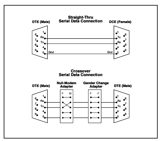
Figure 1: DB-9 Serial Connections
RS422 is very similar to RS232, but uses differential pairs of wires for Tx and Rx to provide better noise immunity (the same as balanced audio and ethernet). RS422 can reliably handle higher data rates than 232, though still not very high compared to ethernet. RS422 was adopted for control of videotape machines and is still commonly seen on video editing and production equipment.
There is no auto-configuration in these protocols, so when connecting devices with any of the serial variants certain parameters must match on both sides. The main parameters are data rate (bits-per-second or baud), word length, parity type, and number of stop bits. A typical RS232 spec might be something like 9600, 8, N, 1. Meaning 9600 baud, 8-bit word, no parity, 1 stop bit. In fact, that’s a good place to start if the specs are unknown. Not all parameters are needed in every case, but interfaces will definitely not work if their baud rates don’t match. Parameters and pins for signaling and flow control (such as RTS, CTS, DTR, etc.) may also be implemented, but most of the time these are not critical for the interface to work.
If you know that two devices will connect straight-through or null-modem, and you have the correct parameters on both ends, the devices can talk. Unfortunately, this information is not always spelled out by manufacturers (or is lost to time) which might mean some trial and error to get an interface working. You may have to experiment with different combinations of baud rate, straight-through and null-modem before data starts to flow, which can be quite frustrating.
In a worst-case situation it’s possible to hang an oscilloscope on the data lines and look for activity under different conditions. This can be helpful to at least identify which connections are Tx and Rx, or if there’s any signal at all. Serial data usually appears as short bursts of well-defined spikes (actually very narrow square waves) above or below 0V.
The information that actually traverses the serial link is generally unique to the equipment being used. There are often descriptions in equipment manuals that indicate the syntax and characters used to send or receive commands. For example, a matrix router might expect a command like “1” “V” “4” to switch video input 1 to output 4. And it might reply with “O” “K” when the switch is executed. Each of those alphanumeric characters is sent as a word in a little burst of bits.
Monitoring that traffic in real time can be done with a terminal program, like PuTTY, and can be useful to see what’s going on with the interface. For example, matching baud rates might be enough to get data moving, but the characters might be nonsense until other parameters are set correctly.
The Plain Old Telephone Service
The telephone system that grew in the U.S. under the auspices of Bell Laboratories and the Bell Telephone companies was the progenitor of many important technologies we still use (balanced audio connections, for one). It was also one of the most dependable and consistent technical systems deployed for the general public. It’s a shame that people have come to expect their phones, computers and everything else to misbehave regularly. This wasn’t always the case.
But I digress. If you spend time behind equipment racks, in server rooms, and in “telephone closets” of office buildings you may encounter infrastructure from old (or still functioning) phone systems. Some old telephone technology is still in use, and sometimes actually necessary, so it’s worth knowing what this stuff is and which wires to leave alone!
Analog telephony (also known as the Plain Old Telephone Service, or POTS) was based on a simple twisted pair of copper wires–essentially one for every phone number in use. Wires made their way from buildings to local offices, to central offices, grouped into larger and larger cable trunks with hundreds or thousands of pairs. A single telco connection is duplex, meaning both sides can talk simultaneously, and within the telephone itself the audio is separated for the microphone and earpiece.
The telco pairs also carried 48VDC power for the phone, which was supplied by batteries at the central offices. This is why home phones rarely stopped working during power failures. Ringing was created by a mechanical or electrical device in the phone, triggered by a higher ring voltage. These voltages are not dangerous, but you would get a surprise if you’re holding the bare wires when it rings!
Telco providers today, who are also Internet Service Providers, want to eliminate the cost and hassle of maintaining the old copper infrastructure, so it is steadily being replaced by “simulated” POTS on broadband internet services. In my case, with Verizon’s home fiber service, there is an RJ11 telephone jack on the fiber interface (ONT) that behaves like conventional analog telco, providing an “off hook” dial tone, DTMF dialing, and other telephone functionality. But only while the interface has power, either from AC or local battery. If the ONT is down, there’s no phone service either.
Speaking of DTMF, this is Dual-Tone Multi-Frequency signaling–the musical sounds of dialing a “touch-tone” phone. Each button produces a different combination of two tones that the central office interprets as the number or letters on the phone buttons. DTMF can also be used to send other types of data over audio lines and was/is used by radio and television stations to trigger remote events, among other things. Before DTMF there was “pulse” dialing, which really is an old technology.
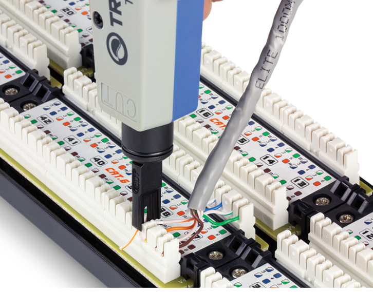
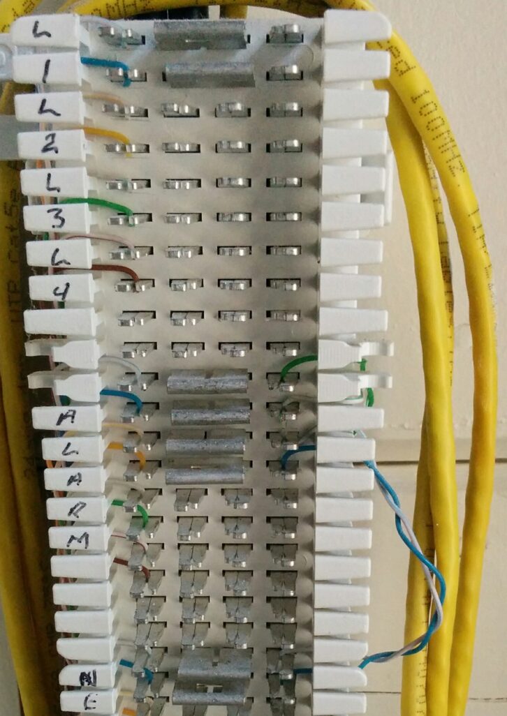 POTS connections in phone closets and machine rooms are generally made with various types of punch blocks. These use metal terminals with slits that slice through the insulation when the wire is forced into them (punched down). This type of termination requires no stripping or soldering, so is very fast. It’s also surprisingly reliable. Common telco punch blocks in the U.S. are the 66 and 110 types, which have their own special tools. The 110 style is also found on network jacks and patch panels. Similar insulation displacement connectors, such as ADC’s QCP terminal, are used in audio patching and termination panels. In most cases the installer can choose to cut off the “tail” of an inserted wire when punched, or leave it intact in order to daisy-chain several connections.
Since the 1970s, connections on phones and other devices use a modular connector similar to the familiar RJ45. This is casually referred to as an RJ11 or 12 (though that is not strictly accurate) and may have 2, 4 or 6 active contacts. In fact, these connectors can plug into the center of RJ45 jacks, which makes it easy to send POTS signals through network wiring. Just keep them away from network equipment! The telephone handset connector looks like an RJ11 but is actually smaller.
The convention for the RJ11/12 pinout in telco is that the first phone line goes on the center two terminals (numerically 3 & 4 in a 6-position plug). Line 1 uses the red & green wires of simple telephone cable, while on trunk cable at the punch block it’s the blue & blue/white pair. A second phone line would go on terminals 2 & 5, with wire colors of yellow & black, or the orange & orange/white pair. The pair colors in ethernet cables originated with telco, but telco trunks use an elaborate color scheme to account for hundreds of pairs.
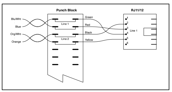
Figure 2: Analog telco wiring
In terms of current usage, I still have clients with legacy telco service for phone bridges that allow outside callers to join a production (such as guests, producer monitoring, or talent IFB). Telco may be used for alarms, fax and ISDN. Sometimes it’s a case of old things being left in place because they work. Other times certain equipment requires a conventional phone connection. These connections might use the original copper POTS lines, if they are still available, or simulated POTS through an ISP. Either way it’s important to understand how the “telephone” part works.
Integrated Services Digital Network (ISDN) is a service that provides high-quality digital audio between locations via phone lines. ISDN was a primary tool for radio stations to do guest interviews, and for long-distance live voiceover work, and even music recording, for some 30+ years. It is being phased out by phone companies for the same reasons as POTS, but is still around.
In telco terminology, POTS and ISDN are sometimes referred to as circuit switched networks because connections are made between endpoints using specific signal paths (circuits) to carry analog or digital data. This is in contrast to packet switched networks, like ethernet, where data is broken into small pieces (packets) that are sent along varied paths and reassembled at an endpoint.
The Resistor Color Code
I’ve been fooling with electronics since I was a kid, which means building a lot of circuits that used resistors. The colored bands on a resistor follow a well-established code that describes its value (in ohms) and tolerance. This in itself is still important! But even if you never touch circuit components the color code may appear in other places–though not consistently across all uses.
One example is multipair audio snake cable with jacketed pairs (such as Belden 1200 or 1400, or Gepco 618 or 724 series). I never have to read numbers on the jackets because the colors follow the resistor code that is embedded in my brain. Multipair that uses white jackets drives me crazy.
Needless to say, I automatically turn to the resistor code when I want to assign colors to numbers for some reason, and I find this with products out in the world as well. If anything, I’m surprised by the number of exceptions that do not use this code. Some examples are colors in multi-fiber trunk cables, colors inside DB9 pin adapters, and colors in some non-jacketed multipair audio snakes. In some cases the color patterns come from other standards, or they developed over time and stuck.
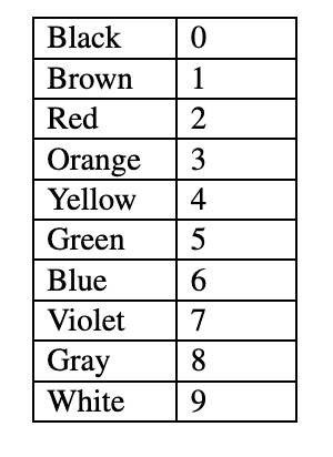
Figure 3: Resistor Color Code Table
Handy links:
https://www.electronicshub.org/rs232-protocol-basics/
https://support.biamp.com/Audia-Nexia/Miscellaneous/Analog_telephone_interface_basics
https://tombuildsstuff.blogspot.com/2015/02/how-to-wire-66-block.html