Video Test Equipment
Feb 1, 2003 12:00 PM,
Chris Steinwand
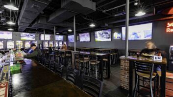
Compared with video, testing and troubleshooting audio is a breeze, and you know what a headache that can be. As more and more installs become an integration of light, sound, and video, the system integrator has to be more versatile and have more knowledge in all of those areas. For this “Technology Showcase,” we decided to tackle video test and measurement equipment.
In order to talk about the equipment, it is important to discuss the procedures. In fact, most of this article is dedicated to outlining the applications. Once you understand the applications, you are better equipped to make sound purchase decisions. This is especially important in video because the equipment is not cheap. Most integrators can’t afford to find out after the fact that they chose the wrong gear for their needs.
Video testing is a broad category with many variables. Creating an article that accurately and effectively conveys the subject matter is a daunting task, at best. While reviewing the technology and the products in the video test equipment category, I found myself scratching my head and wondering where to begin. Then I remembered this wonderful organization called the Electronic Industries Alliance (EIA). This privately held company has been establishing scientific standards of performance, measurement, and testing in all areas of the audio and video industries for decades. Though it has no power to enforce its standards, the work it does is essential for the industry to maintain any coherency. The FCC is a government agency that also establishes certain standards. Unlike the EIA, it does have the power to enforce its standards. While serving an equally important role, the FCC’s approach to the industry and the standards it establishes is totally different.
ESTABLISHING INDUSTRY STANDARDS
Way back in 1957, the EIA published RS-170A. The RS stands for recommended standard. Ironically, 46 years later, it’s still a recommended standard, though it has been in use almost universally since its introduction in 1957. It describes, among other things, the relationship between various sync signals and their timing. The original RS-170 guideline deals with monochrome video, because that’s what was broadcast in 1957. In 1977 the EIA issued a Tentative Standard No. 1, “(To be a future part of RS-170A),” which is a drawing of a color television studio picture line amplifier output. This revision to the recommended standard has been the only one in 26 years. Technically, RS-170A does not formally exist, but manufacturers use this standard in their product designs and in determining if the outputs of certain devices meet the specifications.
The primary purpose of RS-170 and RS-170A is to define the performance requirements of a studio signal — theoretically, the original source of all television signals. This standard spells out the parameters of subcarrier-to-horizontal phasing and color framing. It defines one method for measuring sync timing by defining burst amplitude and frequency. It does not address any test signals or anything concerning picture content. RS-170A is the generally accepted standard by which all NTSC video origination equipment is tested.
RS-250C
Once that “perfect” video signal is generated or produced in the studio, it has to be delivered to some type of video playback device. If the method of delivery is electronic (broadcast) rather than physical (transmitted through a cable), then RS-250C may be used to evaluate the received picture. The EIA has issued a few versions of RS-250 over the years, and version C is the recommended standard. It addresses the problems of electronic transmission equipment and sets the standards for acceptable performance. Using RS-250C requires that you know the transmission path used to deliver the signal. There are specifications for short-, medium-, and long-distance signal paths, as well as satellite and point-to-point transmission. Each path is defined by the number of intermediate processing devices and the type of path. RS-250C deals with coax feeds, microwave, fiber optics, and satellite transmissions as well as combinations of those. Each type of path has its own level of performance standards, and the object of the standard is to assure picture performance as opposed to sync and timing.
RS-250C requires that some video test signals be used to make specific evaluations, and it recommends specific test signals to complete the measurement tasks. A typical example is to specify differential gain at 2 percent for short haul and increase up to 10 percent for overall end to end. In all cases, a method of measurement is defined and the type of test signal to use is recommended. The uses of RS-250C are fairly wide but do not include U.S. broadcast and cable TV delivery systems. Those delivery methods are regulated by the FCC.
NTC-7
NTC-7 is a set of performance standards defined by a cooperative group of network broadcasters (NBC, ABC, CBS, and PBS) in conjunction with AT&T. The definition was developed before the U.S. government decided to break up Ma Bell, and it defined the long-distance delivery of television signals by AT&T for the various networks. It is similar to RS-250C but defines only one delivered condition. NTC-7 is more specific in the test signals used and in the method of measurement. It is useful in that the measurement requirements are very structured, and the document set is clear on the method of measurement of each of the tests.
The world of video test signals can be confusing, but it’s manageable. There are many different signals and many sets of regulations and guidelines concerning the test signals. Some signals look similar to others. So do some procedures, but they do have their differences. FCC color bars differ from EIA color bars, and both differ from SMPTE color bars. Many appear similar, but the differences are enough that if a strict measurement is made of one style of color bars and the results are compared with the requirements of one of the other styles, the values would indicate that the color bars are not correct. A similar problem occurs with multiburst. There are many multiburst test signals available. They have different burst packet amplitudes, and the frequency of the packets can vary from one style to the next. The location (on the line) of the various packets may vary and so on.
To complicate matters further, some FCC tests parameters are different and might seem to conflict with other rules. For example, the FCC requirements allow for burst to be from 8 to 13 cycles, whereas RS-170A limits are from 8 to 9 cycles. The measurement procedures are slightly different, yet a signal can meet both sets of requirements. There are many other conflicts: sync duration, rise and fall times, and others. Typically, the RS-170A rules are stricter. There are also some basic measurement differences. The FCC rules require that horizontal sync time is measured at 10 percent down (typically -4 IRE), and RS-170A makes the measurement at 50 percent down (typically -20 IRE). IRE is a unit of measurement defined long ago by the Institute of Radio Engineers to measure the amplitude of a video signal, whereas 1V equals 140 IRE.
WHY IS ALL OF THIS SO IMPORTANT?
At this point, you might be scratching your head and wondering why all of this information is necessary. All you want to do is install some video in a nightclub. The reason it is important to understand the complexity of video tests and standards is twofold. First, there is no universal set of standards for NTSC video, so the feature sets and performance characteristics of a given type of test equipment can vary significantly from one manufacturer to another.
Second, video test equipment is often a large capital expenditure. You want to be sure that you are making the right purchasing decisions. In order to do that, you have to understand the tests you will be performing and what those tests will tell you about your install.
MEASUREMENT METHODS
Now that I have established a base of reference standards, I can explain some of the most common tests. However, it is important to understand that the standards outlined in this article do not represent a “perfect” video signal. What they do is establish an acceptable range of parameters.
So how do you measure all of these parameters? Because of the complexity and variety involved with video integration, I can’t cover all of the tests or even most of them. What I’ll try to do instead is give you a rundown of the basics.
The first requirement of your measurement tools is that they be capable of measuring to a higher degree of accuracy than you will actually need. After spending thousands of dollars on test equipment, the last thing you want is to discover, in the middle of an install, that your test gear isn’t capable of performing the necessary test.
The general rule of thumb is 10 to 1. It sounds extreme, but your equipment should be capable of accuracy ten times greater than what you actually require. For example, if you need to measure video gain to an accuracy of ±1 IRE, then the measurement tool should have an accuracy of at least ±0.1 IRE. That’s 10 times the resolution. However, you have to balance this rule with a little common sense. To be absolutely scientifically correct, reading differential gain of 0.5 percent requires an instrument with an accuracy of at least 0.05 percent, which doesn’t exist. Then there are the visual recognition and interpretation of the visual results. You look at a CRT trace and compare its position to another CRT trace or to some etched graticule lines. Ten people will read ten different results, all close, but seldom with total agreement. In those cases, the best thing to do is to make several measurements and then take an average of the results.
Another problem area in the method of measurement is that different standards require certain specific test signals for certain measurements, and then they specify the method of making the actual measurement. Some standards require timing to be measured at the 50 percent point of a vertical edge. Others require measurements made at 20 percent or even 90 percent points on the vertical edge. Even amplitude measurement requirements vary from standard to standard. Often the first few microseconds of a sync pulse or window are ignored, but not always. It depends on the measurement and the standard.
A third area of complexity is converting measurement results in formats used by the standards. Signal amplitude may be expressed in volts, millivolts, percentage, decibels, or relative units like IRE. There are methods of translating measurements from one format to the next, but they are not necessarily straightforward unless you’re a mathematician.
The easiest solution to most of these operational problems is automatic measurements. Some of the instruments offered by the manufacturers listed in this article offer measurement devices with preprogrammed standards, values, and methods for performing measurements defined by all of those various standards mentioned earlier. The instruments know whether to make the measurements at the 20 percent, 50 percent, or 90 percent points, they know the format for presentation of resultant measurements, and they even know if the measurement meets the tolerance requirements of the specified standard. All you have to do is tell each instrument which test to perform. This level of automation greatly reduces the amount of training required for a person to operate the test equipment and allows for more consistent results.
TEST SIGNALS
In my research for this article, I counted more than 50 tests that can be performed on a video signal. Many of them are combinations of individual tests, and some are rarely used. To keep things manageable, this article discusses only the most common tests. I will also attempt to cover the most common uses for these tests.
STAIR-STEP
The stair-step signal is ten equal luminance steps from black (7.5 IRE) to white (100 IRE) when viewed from left to right on a monitor or waveform screen. The reason for ten steps is that in earlier days of television, ten shades of gray (from black to white) was the limit of contrast variations possible with picture tubes. There are many variations of the ten-step test signal today. There’s the 5-step, the 20-step, steps that start at 0 IRE, and so forth. But the ten-step test is still the most commonly used.
Stair-step is used as a reference to adjust brightness and contrast on monochrome monitors. It is used to adjust those levels and background (screen) as well as drive levels on color monitors. This signal is one of a few test signals that may be used to check low-frequency amplitude performance and response in amplifiers, distribution equipment, and switchers in video systems.
With a full screen of ten shades of gray, monitor setup can be evaluated in the following areas. Background (screen) and drives may be judged by any color present on the screen. The stair-step should display only black, gray values, and white. If the black steps are tinted slightly red, blue, or green, then the background (bias) controls must be adjusted for each color channel to achieve black. If the whites appear slightly red, blue, or green, then the drive for each color channel must be adjusted to make the whites appear white. This must be done with a calibrated color analyzer that can read SMPTE “C” phosphors. Contrast and brightness may be adjusted with the understanding that a monitor should show the ten steps as ten separate levels on the screen. The PLUGE pattern should be used to set the contrast settings for white level and brightness setting for black level. The correct contrast setting can also be checked with a needle pulse pattern.
Test instruments are available that can measure the light output, color, and intensity from a picture tube. It is possible to use such an instrument to be consistent and accurate. But even if you use these tools, which aren’t always available, you have to temper their results with real-world observations. Always make the final adjustments to a monitor after it has been installed in its final location, because many factors in the room can affect how the colors are perceived, such as the color of the walls and the type of light used in the room.
In system testing, any distortion in the stair-step display when viewed on a waveform monitor can indicate problems. Stretch or compression in any step or any changes in step shape indicates amplifier gain distortions or low-frequency response problems. Judgments are made by viewing the signal on a scope at the test generator source and at the output of the test device. With this test, you can determine if the device itself is distorting the signal. The same test can be performed by connecting the signal generator to one end of the cabling you’ll be using in your install and the scope at the other end to check for line-added distortion.
MODULATED STAIR-STEP
Modulated stair-step is basically the same signal as stair-step but with one color added to the entire signal. This signal is used to measure differential gain and differential phase. On a color monitor, this test signal appears as yellow-green in ten intensities. Differential phase and gain measurement procedures vary with the type of waveform monitor and vectorscope used to make the measurements. The manual for your waveform monitor and vectorscope will usually explain the specific procedures for this test.
The concept of the test for differential gain is to measure the difference in chroma amplitude over various luminance levels. The test signal is generated with exactly the same chroma amplitude on all ten steps. The standard amplitude of the chroma modulated on each step is 40 IRE, but it does vary on some equipment. If you do the testing with a waveform monitor, set the filter to pass only the chroma portion of the video (removing all low-frequency luminance portions). The result will reveal any variance in chroma amplitude (without concern for luminance) or differential gain. Differential phase is any change in chroma phase either against time or because of amplitude variances. On a waveform monitor, use the differential phase or R-Y filter selection. That will give a display of the phase of all chroma in the test signal. The test signal generator makes modulated stair-step at only one phase, regardless of the amplitude. Any difference in phase over the display is measured as differential phase.
MULTIBURST
Multiburst probably has more variations than any other group of test signals. The basic versions are called low-band packets, high-band packets, low-band sweep, and high-band sweep. There may or may not be markers used in these signals, and there could also be user-controllable markers. All versions of multiburst have one thing in common: they all include many frequencies and present multiple frequencies over time. The time may be measured in portions of a horizontal line (packets) or over the period of an entire field of video.
The most common of these signals is low-band multiburst, which contains a white bar and six packets of fixed frequency in 25 to 75 IRE (or 0 to 100 IRE) transitions. This test signal is used to evaluate signal amplitude versus frequency in television systems. The most common burst frequencies are 0.5, 1, 2, 3, 3.58, and 4.2 MHz. Tests usually entail observing each multiburst packet amplitude, passing the test signal through a device under test, and again measuring the amplitude of each packet. Any variance in amplitude in any of the packets shows a gain variance at that frequency in the unit being tested.
Most video systems distort multiburst by reducing the overall amplitude of each packet, and the higher the frequency of the packet, the greater the reduction. Other distortions are also possible. Color reproduced by videotape recorders often does peculiar things to the 3.58 MHz packet. The signal can actually end up with greater amplitude than when it was recorded.
The frequency response of the device or system is tested by measuring the amount of reduction of the multiburst signal at specific frequencies.
COLOR BARS
Color bars are a better-defined test signal, but there are still a few variations in use. Almost all have the same primary and secondary colors presented in the same manner. A few have reverse bars, I and -Q bars, PLUGE test signal, or all of those. The most common in use today is the SMPTE color bar test signal.
The SMPTE color bars are divided into three bands of signals. The top or first band contains the traditional six colors and gray. From left to right they are gray, yellow, cyan, green, magenta, red, and blue. The middle band contains reversed bars with every other bar set to black. The third band contains the I, white, -Q, black, and PLUGE signals. The color bar signal is used to align color monitors and to check color phase and amplitudes.
Monitor setup with these color bars is fairly simple. The first step is to use the stair-step signal and the alignment procedures mentioned previously. Then, with SMPTE color bars on the monitor, again adjust brightness so the 3.5 IRE PLUGE signal just disappears. The PLUGE signal is three steps of gray from 3.5 to 7.5 to 11.5 IRE units in the lower-right corner of the viewed signal. If you can’t see it, adjust brightness to raise the black level toward gray. Then, reset the brightness to make the lowest step just disappear. Next, turn on the blue gun only. Adjust the monitor hue (phase) so that there are four blue bars separated by three black bars. Then, adjust the color (chroma) so the outer two blue bars match between upper and middle bands. Finally, fine-tune the phase so that the middle two bars match between the upper and middle bands. If required, fine-tune hue and color so there is no visible difference between any of the blue bars in the first and second bands.
There are other system applications for color bars. They are useful in VTR testing and for quick checks of system color phasing through monitors and vectorscopes.
RED SCREEN
The red screen test signal is used almost exclusively in color picture monitor setup and testing. This test signal is a composite video signal with sync, reference subcarrier color burst, and a full field of color video. The video varies by manufacturer, but it is almost always a red that will lay in the red box in a vectorscope. That means the red is a specific hue and saturation, relative to reference burst. The primary variation is the luminance value of the red field. Most red screen generators present a red with the same luminance values as the red in color bars. While this is common practice, there don’t seem to be any official guidelines for red screen patterns in any of the reference standards.
Because red screen is primarily used in color monitor setup, you can assume that if the signal is identical to the red in color bars, you know how the video should look on a monitor. You can then use the signal to check monitor performance in purity and degaussing operation as well as to evaluate the magnetic effects of the immediate environment on the monitor in test.
Before using the red screen signal, use color bars and gray-scale signals along with the procedures described previously to adjust the brightness, contrast, color, and hue to the correct values. You can then connect the red screen signal to the video input of the monitor being tested. The screen display should now be red and only red. The entire screen should be one shade of red, with no variations of hue, color intensity, or saturation anywhere on the screen. If that is not the case, then some adjustments are needed. It is often difficult to determine the source of the problem, but the cause is always related to magnetism. There are two primary contributors to this distortion: the magnetic state of the environment and the magnetic state of the monitor. The monitor has two separate circuits to deal with magnetism, which are the degaussing coil and the color purity rings and magnets. Thus, you do have some control over the magnetic state of the monitor. Unfortunately, you can’t degauss a room, but in many cases, a magnetic source can be relocated or shielded to prevent interference with the video monitor.
Rotating a monitor 90 degrees to the left or right can sometimes cause drastic changes in the appearance of the red screen signal, indicating possible magnetic-field interference. Loudspeakers and other electromagnetic devices may add to the magnetic field. That is easily proved by relocating any nearby speaker or by turning other devices on and off. Equipment racks may become magnetized, a condition that can be diagnosed by moving the monitor under test in and out of the rack while observing the screen.
Turn the monitor under test to off, wait a few minutes, and turn it on again. There is an internal degaussing coil in almost all color monitors that will neutralize residual magnetic fields within the monitor. Usually, that is enough to deal with relocation and minor changes in the environment. It cannot deal with the effect of loudspeakers and other strong, variable external magnetic influences. Handheld degaussing coils are available to assist the internal coils, to neutralize the monitor case, and to neutralize magnetic objects, including equipment racks.
In this “Technology Showcase,” rather than listing the multitudes of specific product models and attempting to compare features and specifications, I instead provided a reference chart listing many of the top manufacturers of video test equipment and the product areas in which they have offerings (see the sidebar “Video Test Equipment Manufacturers”). Because this is a complex product group with many variables, I strongly encourage you to spend some time going through each company’s Web site. In fact, much of the information presented in this article was gathered from application notes found on some of the Web sites. Visit them yourself; you’ll not only find plenty of product information, but on several of the sites, you will find excellent reference material to further educate yourself on this subject.
For More Information
AccuPel
www.accupel.com
Ž 207
Astro Systems
www.astro-systems.com
Ž 208
BK Precision
www.bkprecision.com
Ž 209
Burst Electronics
www.burstelectronics.com
Ž 210
Evertz Microsystems
www.evertz.com
Ž 211
Extron Electronics
www.extron.com
Ž 212
Hamlet
www.hamlet.co.uk
Ž 213
Horita
www.horita.com
Ž 214
Leader Instruments Corp.
www.leaderusa.com
Ž 215
Magni Systems
www.magnisystems.com
Ž 216
Multidyne
www.multidyne.com
Ž 217
SyntheSys Research
www.synthesysresearch.com
Ž 218
Videotek
www.videotek.com
Ž 219
Sencore
www.sencore.com
Ž 220
Tektronix
www.tek.com
Ž 221
Ž Circle this number on Reader Service Card or visit freeproductinfo.net/svc